Inductors are rare for hobby electronics. However, they’re essential to learn about if you’re doing anything that involves alternating current (AC). They’re as popular as resistors in applications that use AC. They impose changes in the flow of current. As a result, they are great for filtering signals and transforming between different AC voltages. This is why we often use them in variable power supplies. These are only some of the reasons why you should learn about inductors. Nevertheless, this guide will explore some of the Inductor Basics.
Contents
What is An Inductor?
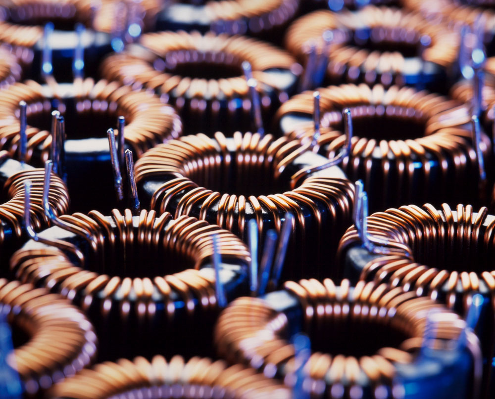
A set of inductance coils
An inductor is an electronic component that transiently stores energy. Consequently, it uses a magnetic field to achieve this. Generally, most inductors appear as a coil of wire (often copper wire) around a magnetic or nonmagnetic former. Formers can use the following main types of core material:
- Iron Core
- Ferrite Core
- Air Core
- Ceramic core inductors
Consequently, ferrite and iron core inductors may be the most preferable because they can generate larger magnetic fields and thus store more energy.
How Does An Inductor Work?
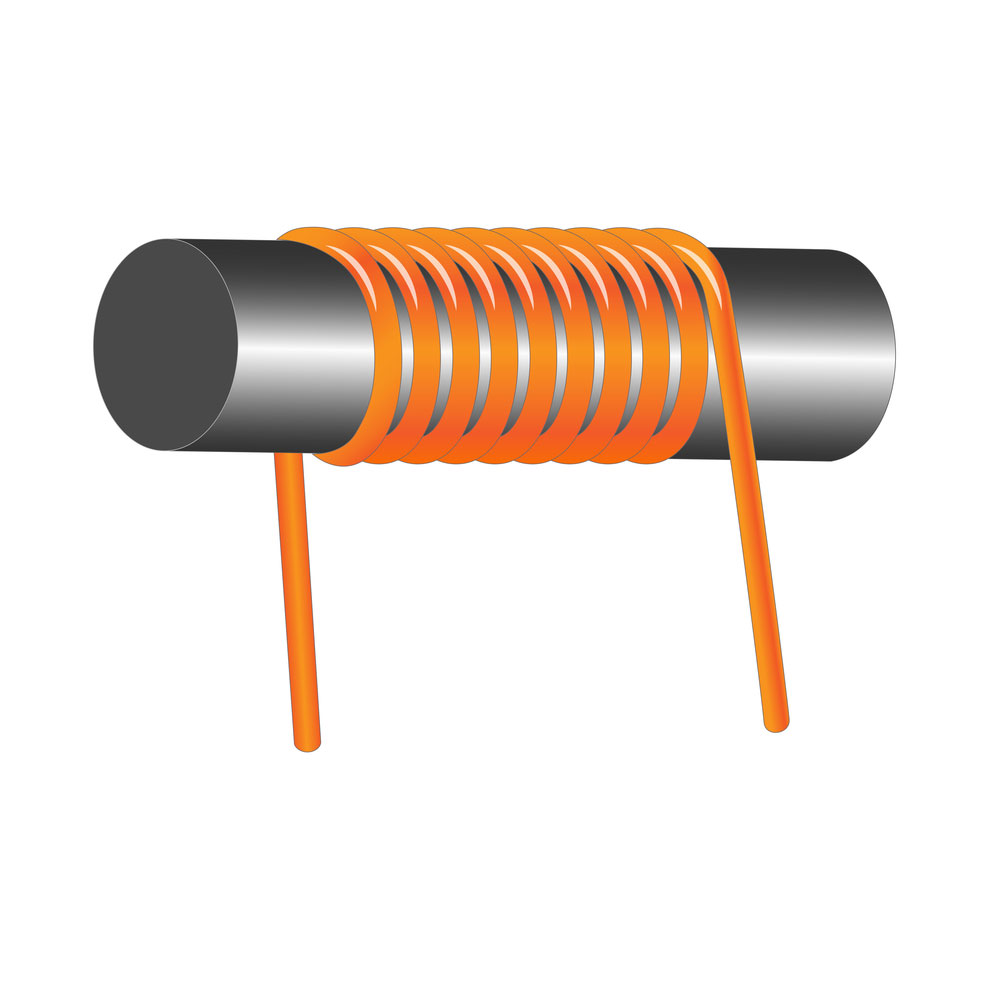
An inductor
As you may have noticed, inductors don’t necessarily require formers to function. Most air inductors are tightly insulated wire wound together without a center. Because of Faraday’s Law of Induction, when an electric current passes through a coil, it creates a magnetic field.
When we coil a cluster of wires, this can create an even larger magnetic field. As current flows through this cluster, it becomes magnetic energy. However, when the current stops flowing, the electromagnetic field breaks down, and the magnetic energy transforms into electronic energy. In this stage, it mimics a classic piece of wire.
However, it takes a while before the inductor transforms and releases all magnetic and electric energy, and this is the basic concept of electromagnetism which all inductors function on.
To illustrate, we can think of inductors as large waterwheels. When you have a heavy stationary waterwheel and start flowing water through it, it will take some time and energy to get the wheel up and spinning. However, once it starts spinning and has substantial momentum, it will take time to stop spinning when you cut off the water supply. Inductors function on the same principle but with an electric charge.
This resistance to electric flow is what we know as inductance. It describes the ratio between magnetic flux and the electric current that induces it. There are a wide variety of different types of inductors on the electronics market. They all have their own unique basic properties, constructs, and purposes.
Differences Between Inductors and Capacitors
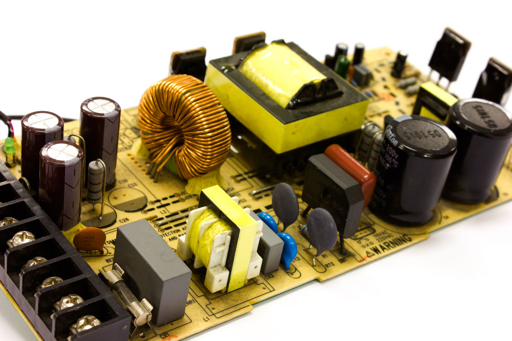
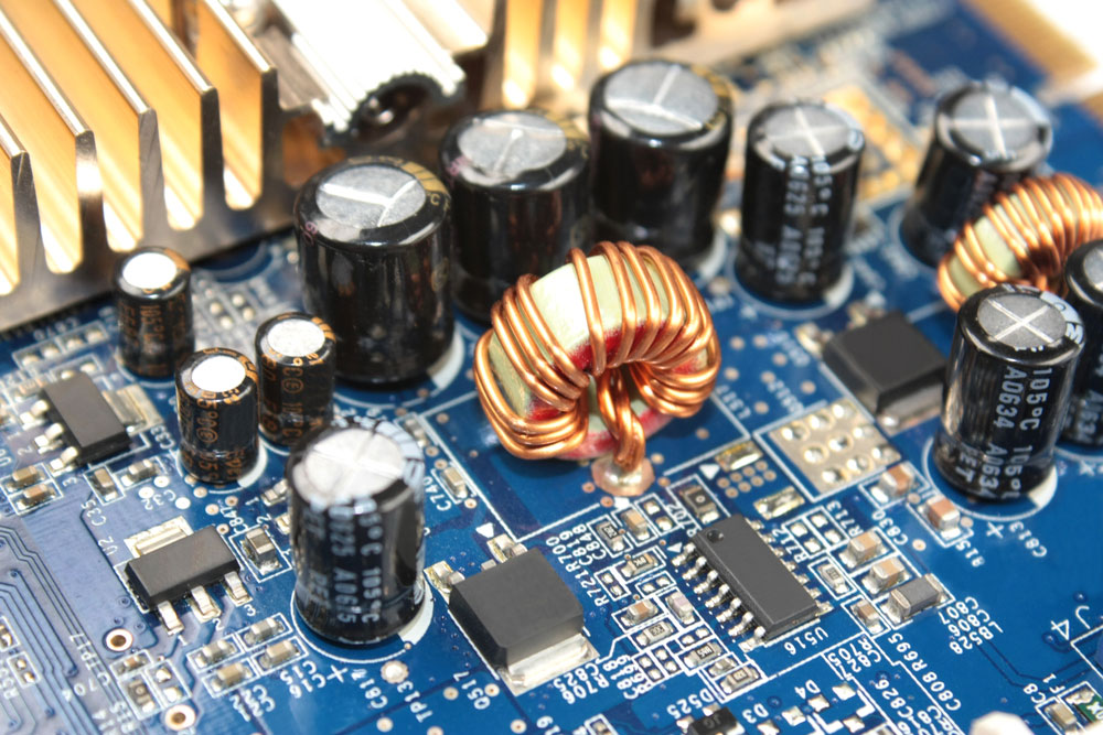
Power supply board capacitors and inductors
While inductors and capacitors serve similar functions, they work pretty differently. They both are passive components that store energy from a circuit and then discharge it. However, a capacitor stores energy in an electric field. In contrast, inductors store energy in a magnetic field and release it as electrical energy. Consequently, this is a process that we know as electromagnetic induction.
Notably, this is where inductors get their names. Nevertheless, we generally use capacitors in high-voltage electrolytic applications such as power supplies.
We can also use them in lower voltage applications and general purposes where we require large capacitance values. On the other hand, we use inductors in and AC applications like radio TV.
Inductor Symbol
We measure inductance using the SI unit of inductance, which we know as the Henry (H). It gets its name from Joseph Henry, a prominent scientist who discovered mutual inductance. Nevertheless, the different electronic symbols for inductors look like this:

How To Measure Inductance
Before we can explore how to measure inductance, we need to examine which factors influence inductance.
Factors Influencing Inductance
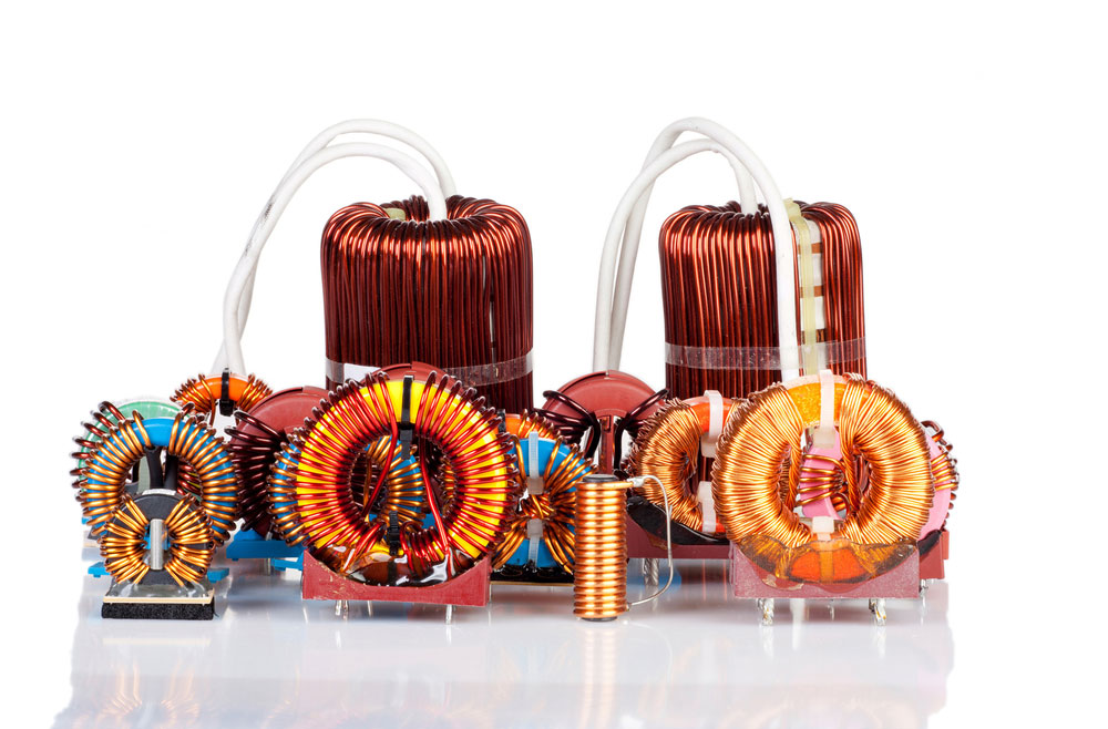
A collection of industrial choke inductors
We can determine the electromagnetic inductance of an inductor by four main factors:
- Number of turns of the coil (N)
- Core material and permeability (μ)
- The cross-sectional area of the coil (A)
- Length of the coil (l)
Inductance is directly proportional to permeability. If we increase permeability, we increase inductance. Let’s consider the air core inductor. Air has a relative permeability of 1 (μ = 1). This is because air, much like ceramic, has virtually no magnetic properties, and thus it does not enhance the coil’s inductance in any way.
If you require an inductor with higher inductance, you should consider using a core with magnetic material or ferromagnetic material. Incidentally, magnetic core inductors have permeability that ranges in the hundreds (μ = 100+).
As such, they provide a significantly higher inductance for the same size inductor. This is why manufacturers tend to avoid building air-core inductors. While you may think it’s a good idea to use core material with the highest permeability, it’s not because the core material type affects power and thermal efficiency.
Ferrite and metal composite materials are two types of cores that manufacturers commonly use in conductors. Each type of material has strengths and weaknesses. For instance, ferrite material tends to have very high permeability and high inductance value for a given package size.
However, thermal instability may be a factor that dissuades people from choosing this core material. Operating incoming current above the saturation level may lead to overheating and failure of the electronic circuit.
Metal composite cores tend to be more desirable because of their softer saturation characteristics. This may be closer to your ideal inductor. Nevertheless, when choosing an inductor, these are the factors you need to consider. They control and influence the inductor’s electromagnetic properties.
How To Calculate the Microhenries of an Inductor’s Coil
To find the inductance of a coil, you’ll need to measure the length(L) and diameter(d) of the loop, as well as count the number (N) of turns (or rings in the loop). Next, you must square both the number of turns (N^2) and diameter(D^2). Next, you’ll need to multiply the squared figures by each other. In a separate calculation, multiply the diameter by 18 (18D) and add it to the length, which you multiply by 40 (40L).
Divide the first equation by the second equation. Your final equation will look like this:
μH = (N^2)(D^2) ÷ (18D + 40L)
The above calculations will reveal the microhenries of a coil. To convert microhenries into henries, you’ll need to take the result of the above analysis and divide it by 1,000,000. This is because:
- 1μH = 0.000001H
- 1H = 1000000μH
You can find online coil inductance calculators or purchase inductors of a known value to make it easier for yourself.
Inductors in Series and Parallel
Just like putting resistors and capacitors in series and parallel, you’re most likely going to want to do the same thing with inductors. As a general rule of thumb, inductors add in strings and parallel the identical way resistors do. Thus, the equation for resistors in series and parallel is similar for inductors.
Inductors in series add together just like resistors. Let’s say you have two inductors in series (L1 and L2). The equation will look like this:
Total = L1 + L2
This makes sense because it’s the same current going through all of the inductors. Thus, if there’s a change in the draft, the difference in all the inductors is the same. When we connect inductors in parallel, the total inductance will be less than each inductor.
Accordingly, each inductor is experiencing less than the total amount of electric current going through the electrical circuit because the electric current splits up. As such, the ratio of the magnetic flux to electric current is different. Thus, the equation will look like this:
Total = 1/(1/L1+1/L2)
Energy Stored By an Inductor
In this section, we’ll explore how to calculate the amount of electric energy in an inductor.
Let’s take an example where a current of 15A (Amperes) flows through a 200mH inductor. The energy stored is 1/2 the inductance multiplied by the square of the wind.
The template for our equation looks like this:
U = 1/2L * I^2
Using our example, the first step we need to take is to convert mH (millihenrys) into H (henrys). To do this, you’ll need to multiply the mH inductance value by 10^-3. Thus, the calculation and result will look like this:
200mh * 10^-3 = 0.2H
Once we have our inductance in henrys, we can calculate the magnetic field’s energy. The calculation looks like this:
U = 1/2(0.2) * 15^2
U = 22.5 Joules
This is the standard equation to calculate stored energy in an inductor’s magnetic field.
Inductor Applications
The inductor as a choke on a circuit
We briefly touched on some of the uses of inductors in the above section. Nevertheless, let’s take a closer look and expand on some of these applications. We use inductors for:
- Boost converters where they help increase the direct current (DC) output voltage while decreasing the current
- To choke alternating current supplies and only allow direct current (DC) to pass through a circuit
- Separation of different frequencies
- RF circuits, analog circuits, and tuned circuits
- Motors, transformers, relays, and a wide range of other electronics and convertors
These are the most common inductor applications, and we can also use higher frequency inductors in radio applications.
Summary
It’s important to remember that you cannot measure inductance with a standard multimeter. However, you can find specific models with a built-in RLC meter. However, it won’t reveal the most accurate result to you. To measure inductance correctly, you need to use an RLC meter. You can connect the inductor to the unit, and it will run a quick test to measure the values. Alternatively, you can use some of the information in the above guide to figure out how to calculate inductance yourself. Nevertheless, we hope that you’ve found the above text to be helpful. As always, thank you for reading.


