Using a MOSFET transistor, we can control the voltage or current flow between the source and the drain. Also, there are different types of MOSFETs. The N-channel type Mosfet is one of these. The N-channel Mosfet is a metal oxide semiconductor field-effect transistor(FET). We often use it for voltage control. This article will discuss the irf740 Mosfet, which is under the N-Channel Mosfet. Additionally, this article should help you learn how to use the irf740 in your circuit connections.
Contents
What is The Irf740?
The irf740 is an n-channel power MOSFET transistor that can switch power loads up to 400v. These electrical components can switch loads that use up a power of up to 10A. The irf740 is essential in applications that require switching from one source to the next in seconds. However, between the gate pin and source pin, you need to place a gate threshold voltage of about 10v. This gate charge helps the Mosfet to perform its switching efficiency.
Moreover, when using an irf740 transistor, you can build a simple driver circuit. You place this driver circuit by the gate pin. This step should provide the Mosfet with a threshold voltage of 10v. The Mosfet is likely inefficient when you require it for electrical switching purposes without the driver circuit.
Notably, the irf740 N-Channel is affordable and has good switching speeds needed in a DC-DC converter. Also, it has a meager thermal resistance. However, like every other electrical component, the irf740 also has drawbacks. The irf740 Mosfet transistor has a 5.5 OHM high on-resistance, popularly known as RDS. This property makes the irf740 inefficient when you require highly high switching applications.
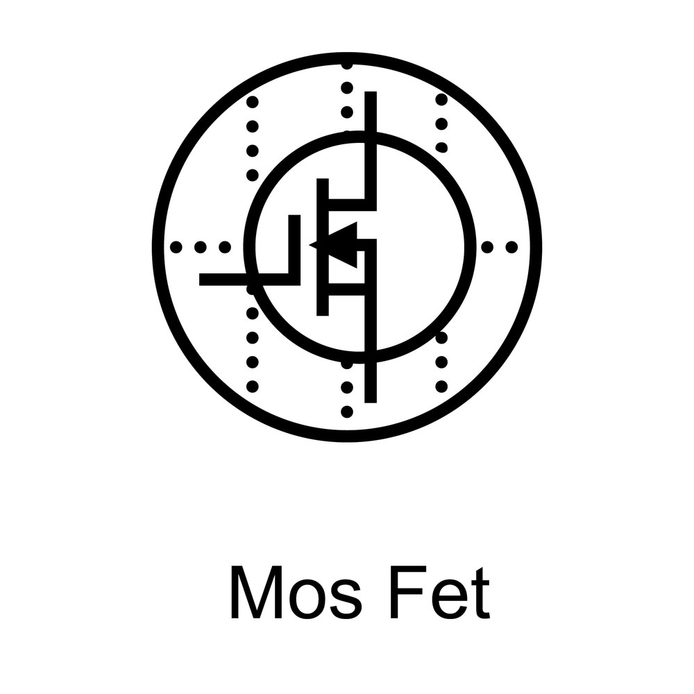
(a symbol of a Mosfet)
IRF740 pin Configuration
The irf740 N-channel power Mosfet has three pins. The table below shows the detailed descriptions of each nail.
| PIN NO. | NAME | DESCRIPTION PIN |
| 1 | Source | A maximum load current of 10A flows out through the source. |
| 2 | Gate | Controls the biasing of the Mosfet using a threshold voltage of 10v |
| 3 | Drain | Allows current to flow through it. |
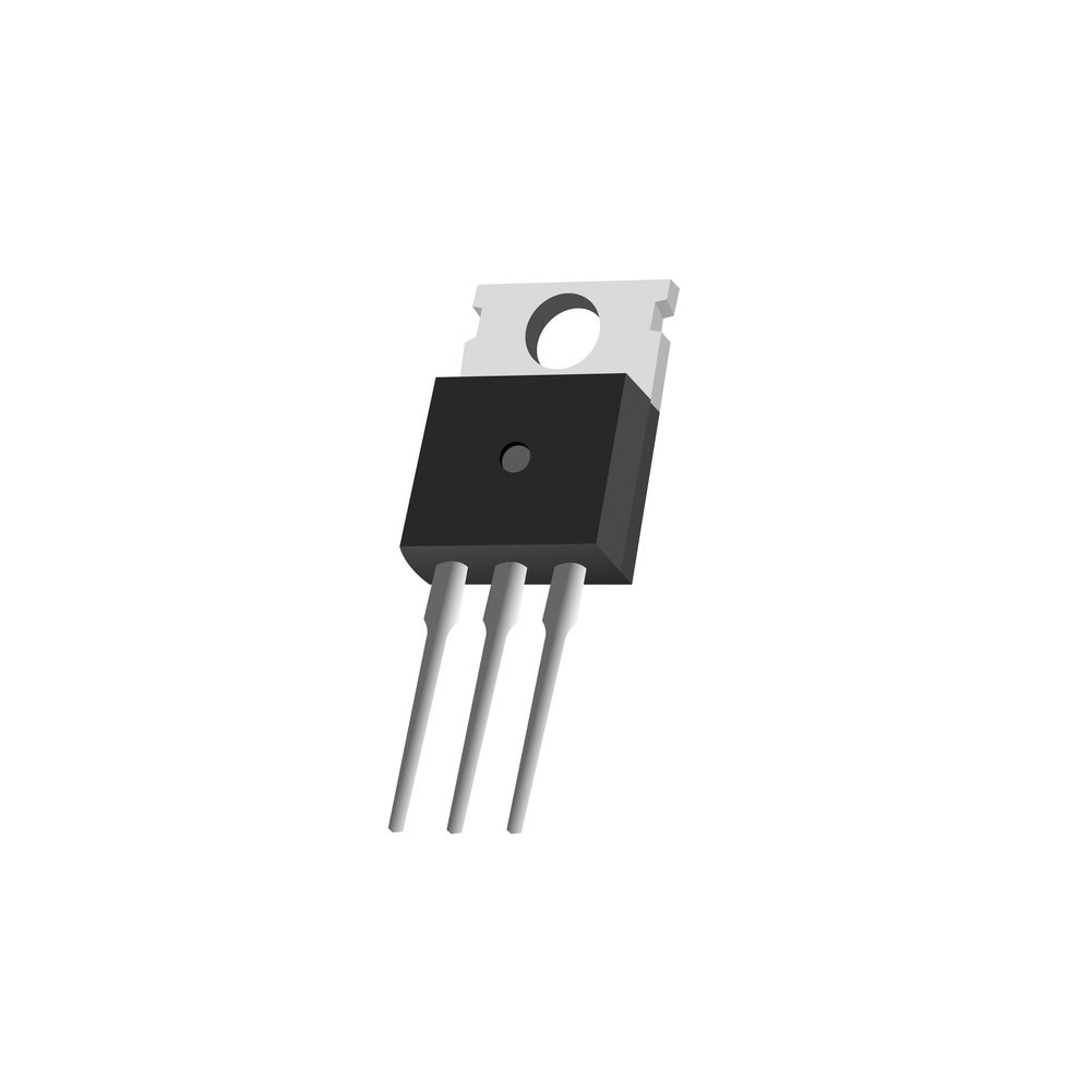
(a three-pin configurated transistor.)
IRF740 Features and Characteristics
Below are some of the notable characteristics.
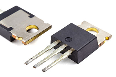
- Firstly, you can find the irf740s Mosfet N-CH in a TO-220 package.
- Secondly, the irf740 is an n-channel power Mosfet.
- Thirdly, the rise time of the irf740s MOSFET N-CH is 27ns while its fall time is 24ns.
- In addition, the irf740 has a continuous maximum drain current of 10A.
- Also, the minimum voltage needed to conduct is between 2v and 4v.
- Next, it has a 400v drain to source voltage.
- Additionally, the irf740 has a maximum power dissipation of 125W.
- Also, the irf740 has a 10v gate threshold voltage, although the maximum current is 20v.
- Moreover, the operating temperature and maximum storage should be between -55 degrees Celsius and +150 degrees Celsius.
- Lastly, this FET type N-Channel has a 0.55 ohms drain-source resistance.
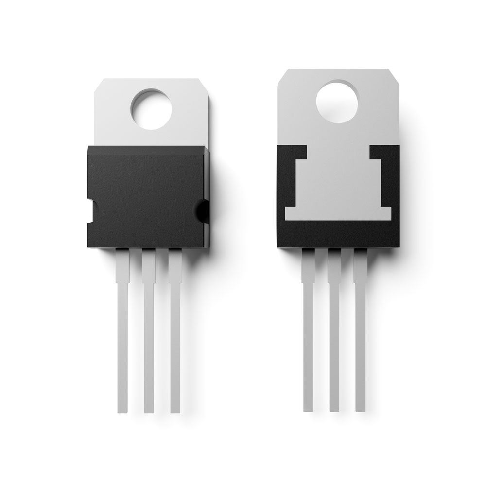
(examples of transistors with TO-220 package.)

Replacement for irf740s
These include the IRFB13N50A, ssf13n15, and UF450A.
Applications
- Firstly, you can use it in DC-DC converters.
- Secondly, you require it in inverter circuits or battery charger circuits.
- Also, the drive voltage helps in controlling the speed of motors.
- Additionally, used in UPS.
- Moreover, It is essential for high-speed switching purposes.
- Additionally, you can use this transistor in the LED dimmers and flashers.
- Lastly, you can use this Mosfet N-CH in switching a high-power device.

(motors in different sizes.)
How to Run irf740 Safely in the Circuit
For any electrical component to last long, it is necessary to use it just 20% below its maximum ratings. This property is also essential when using the irf740s.
As discussed above, the maximum continuous drain current of this irf740s Mosfet N-CH 400v is 10A. However, the inductive load to be driven should not surpass 8A.
Similarly, this property applies to the drain to source voltage. Since the max load voltage is 400v, the drain voltage should not surpass 20% below the maximum rating mark.
Moreover, always operate and store the transistor within suitable temperature conditions. Also, consistently ensure to use a heatsink during operation.

(a group of different electronic components.)
Summary
The design of the irf740 is specifically for high voltage and fast switching purposes. This tip is necessary, especially if the user wants to change the input power from one load to another.
We hope this article has been of help to you. For any queries or services on this or any of our articles, please do not hesitate to contact us.


