
A lead-acid battery charger circuit is a valuable power source for most systems, and you’ll find it in the motorcycle battery. Also, it is a simplistic circuit that facilitates charging common 12-Volt SLA Battery types.
Hence, It is essential in charging backup power systems. Different battery manufacturer gives various charging techniques. However, the bottom line is that the underlying system is the lead-acid battery charger circuit.
Check out our elaborate presentation of the circuit for further understanding.
Contents
What is a Lead-acid Battery Charger Circuit?

Fig 1: Changing a Car Battery
A lead-acid battery charger circuit is used to charge standard backup power systems. Such a battery will require a current-limited power supply that maintains a constant voltage across its terminals, and you must supply it with the correct current. Giving such a current at the required rate is where this circuit comes in handy. It will provide a sufficient charge to the battery and disconnect when it is complete.
Important Parameters to be Considered When Creating the Circuit
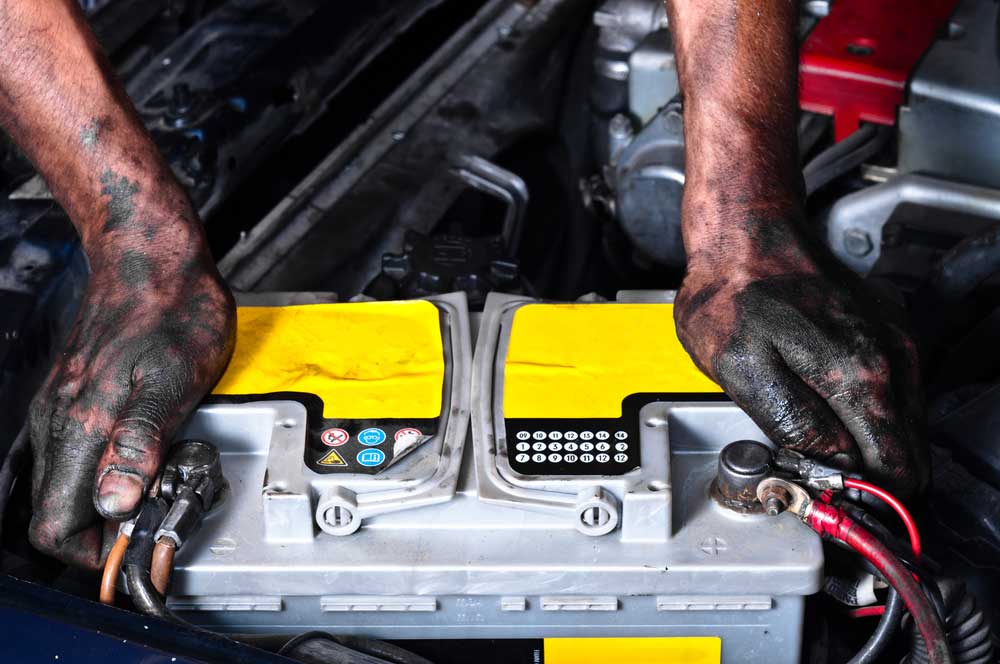
Figure 2: A Mechanic Changing a 12V Lead-Acid Battery
All battery products have a battery-printed voltage, and it will depend on battery size. Hence, to keep the battery healthy, ensure you supply the actual battery voltage.
Otherwise, you will not avoid battery malfunction.
Also note, there are important parameters for all battery technologies that you should consider. Every charger must fulfill each of the following:
- Since an unregulated power supply will spoil the battery, the charger must deliver constant current. If the current decreases, the battery will undercharge.
- It must provide a battery voltage level at least 17% more than the battery printed voltage.
- Although this is not a compulsory requirement, it should have a float charge, and its essence is to prevent battery self-discharge.
- It should cut the current rate when the battery attains the threshold level.

Components of Lead Acid Battery Charger Circuit
Circuit Diagram
Here is the complete circuit diagram of this battery charging process.

Figure 3: A Lead Acid Battery Charger Circuit
Components
For an assembly of backup batteries charger systems, you will require the following parts:
- Bridge Rectifier: It will convert AC input current to DC. Hence, it is essential in the delivery of the proper current type.
- Resistors: They will aid in the control of the current levels.
- Two Diodes- a Zener and a 1N4007: They will be helpful when the circuit attains a tripping voltage.
- A green LED or any LED display.
- A potentiometer: It will give the circuit’s potential difference.
- A 12V Relay: It will keep the circuit operational even when the power is off.
- An LM 317 IC: It will facilitate the maintenance of a constant voltage. Hence, it is essential in improving the battery life.
- A 7815 voltage regulator: It is among the common voltage regulator types. It produces a constant voltage of 15V.
Calibrate the Circuit
Before explaining the battery charging process, let us first look at how to calibrate the circuit. For this process, you require a bench power supply.
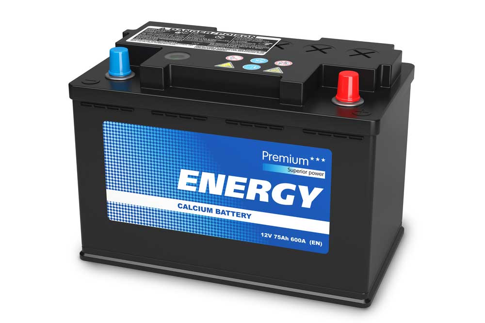
Figure 4: A Lead Acid with Manufacturers Logo
During calibration, ensure that the DC power supply is at 14.5V. Connect the power to the positive and the negative terminals of the circuit. Set the jumper on calibration mode and turn the potentiometer knob until your LED turns to red color. Once you attain this level, disconnect the power supply and reset the jumper to use mode. Your circuit is now ready for use, and you can connect it either to an AC or DC power supply.
Also, you must note the following:
- We have set the power supply at 14.5V, which is the circuit’s tripping point. When you set the circuit to this point, you will achieve approximately 75% of the charging percentage.
- You can boost the charge percentage to a higher value, such as 100%. However, for this, you will require to eliminate the voltage regulator. It will set the tripping voltage at approximately 16V. Nonetheless, avoid such a setting as it delivers about 18V to the battery.
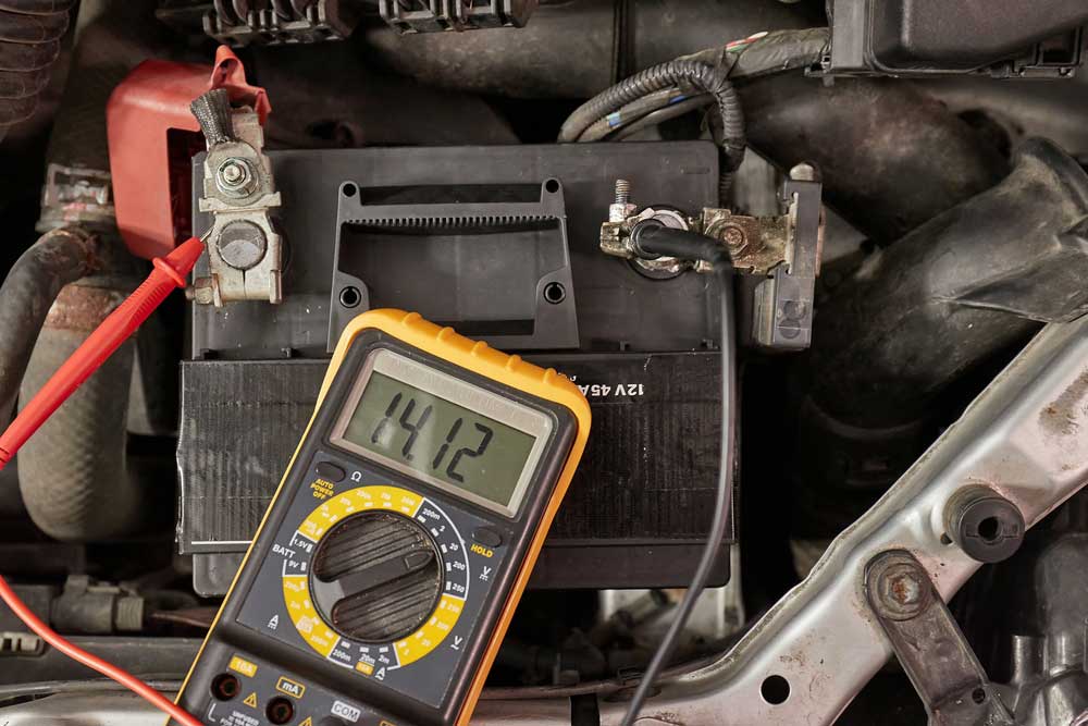
Figure 5: Checking the Performance of a Lead Acid Battery
Circuit Explanation
Note the following for this circuit:
- You will connect the DC voltage to the voltage input of the voltage regulator. The power supply will charge the battery via the resistor and relay.
- The Zener diode becomes active when the circuit attains the tripping voltage. The aim is to ensure that the transistor has sufficient base voltage.
- The result of the above process is the activation of the transistor. Consequently, it will gain a high output. Also, the signal will prompt the relay to switch on, which will disconnect the battery.
Different ways to charge using the Lead Acid Battery Charger Circuit
You can use various ways to charge the lead-acid battery circuit. We’ll look at each one of them in detail here below.
Using a Single Op amp
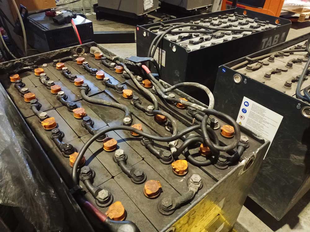
Figure 6: Industrial Lead Acid Batteries
Here are the simple steps to understand the working of this circuit. First, you will configure the system using three simple steps. For instance, there is the power supply phase. In this stage, you will need a bridge rectifier network and a transformer.
During configuration, you can ignore installing a filler capacitor in series with the bridge rectifier. Nonetheless, to improve the DC output, consider inputting it. Preferably, a 1000uF/25V capacitor is the best for this use.
Also, remember to connect the output of the system to the battery you want to charge.
Next, you need to connect a 741 IC voltage comparator, and its essence is to detect the battery voltage during the charging process. Connect this IC to the battery but remember to use a 10K preset in the connection.
The preset will be handy in facilitating the reverting of the IC when the battery gets full.
It would help if you also connected the IC to a voltage divider network. The components of this network will include a 6V Zener diode and a 10K resistor.
Also, connect the IC’s output to the relay driver stage. In this step, you need to have a transistor for the control of the circuit.
Here is what happens when you connect the circuit: Upon clicking the switch, it facilitates bypassing of the relay. Consequently, the course goes on, albeit for a short while.
Next, the IC will detect the battery’s voltage. Since the levels are low, the IC will prompt the creation of common logic output. Resultantly, the relay and the transistor will go on. The relay’s role here is to hold on to this power so that the circuit remains operational even if the switch is off. Thus, the battery will start charging.
When the charge level approaches 14V, the IC once again detects it. Accordingly, it switches to high logic output. In response, the transistor will turn off the relay. At this juncture, the circuit will go off, and it will remain off until you turn it on once again as it is at maximum charge capacity.
12V, 24V / 20 amp Charger Using two opamps
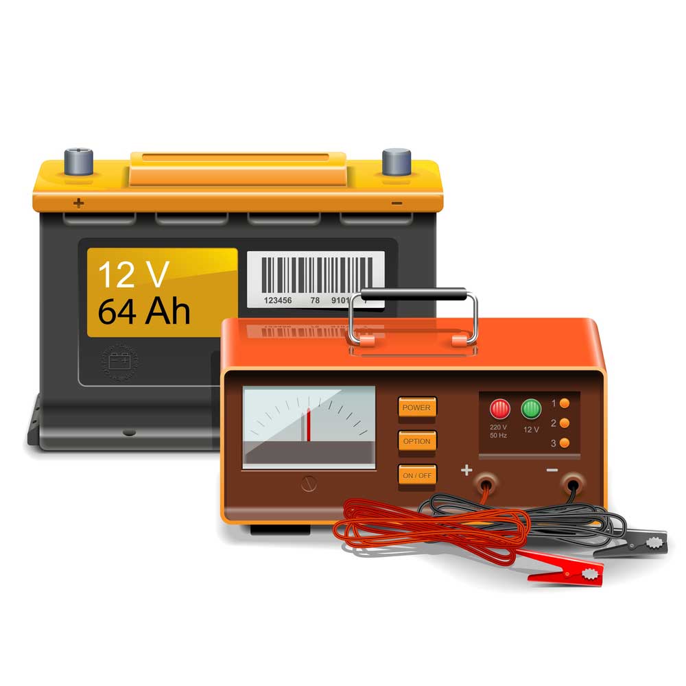
Figure 8: Checking the Volage Levels of a Lead Acid Battery
Here is the second option. It will operate under a similar principle to the first one.
When there is no battery, the circuit will be off. The relay during this phase keeps the connection off.
Now, consider a case when you connect a battery without charge to the circuit. The circuit will switch on. Next, the IC will detect the low potential and prompt the beginning of the charging process.
However, note that in this circuit, the two op-amps work in tandem. They will facilitate the hysteresis process during charging, and both also work to reverse the hysteresis process when the battery level goes to another low.
Using IC 7815

Figure 9: Several ICS
You can charge the battery without using a relay or IC. For this, you will need an emitter follower sort of circuit. It means that the emitter will only allow the operation of the transistor if its potential is below the base potential. The action will occur when the emitter potential is low by approximately 0.7V.
The use of the IC 7815 is to provide a regulated voltage of 15V. As a result, the potential difference will be the difference between 15V and 0.7V. Hence, 15V – 0.7V is 14.3V. Therefore, the 14.3V is the threshold upon which the battery disconnects and ceases charging.
12V 100 Ah Lead Acid Battery Charger Circuit
You can also create this circuit using IC 78H12A. Nonetheless, it would help to be keen on the system’s voltage before connecting it to the battery. The aim is to guarantee compatibility.
During connection, you will require several diodes. Four of them can be 1N4007. Also, ensure that the others have ten amps and above rating. You can achieve this by connecting 6A4 types of diodes.
Also, in this circuit, installing a heatsink is imperative for effective heat dissipation, and it will facilitate the efficient operation of the course.
IC 555 Lead Acid Battery Charger Circuit
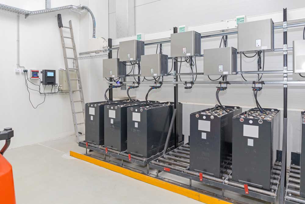
Figure 10: A Car Battery
Lastly, this form of the circuit will aid you in charging any size of a battery. You can connect it in two primary ways, and they include the following:
Using IC 555 as the Controller IC
In this circuit, your IC 555 will operate as the comparator, facilitating the comparison of the battery charge conditions. The power supply is also anything but sophisticated, and all you need is a bridge network. Also, when choosing the diode rating, consider the battery’s charging current rate.
Always ensure that the diode rating is double the battery charging current rate. Also, you must provide the battery’s Ah rating is ten times its charging current rate.
IC 555 Current Dependent Battery Charging
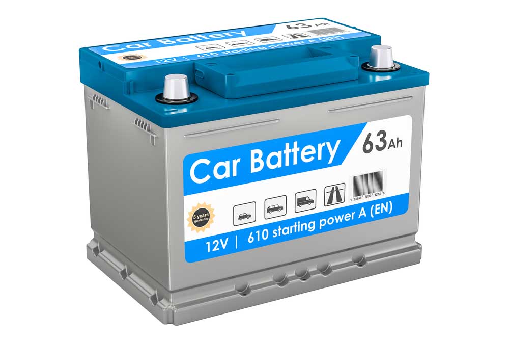
Figure 11: A 12V Car Battery
Connect this circuit as a reset latch system. When you first apply power to the system, it will initially not start, and at this point, it will disconnect the relay contact. Also, note that the battery is at this instance load.
Next, when you turn on the relay, it will prompt the switching of the circuit. Current will, as a result, flow. Similar to the other courses, the relay will shift the gain depending on the wind.
Conclusion
A lead-acid battery charger circuit is one of the fundamental electronic systems, and you would help if you had it in charging the battery systems of all lead batteries. Thus, we have given you all the crucial info for a complete understanding of its working principles.
We are your trusted site for information on electronic components. Reach out to us anytime you have queries, and we will respond instantly.


