Contents
What is LM1875?
LM1875 is a monolithic power amplifier IC from Texas Instruments with five terminals. It can function in a dual or single rail power supply and has built-in protection to ensure durability.
Further, it uses a few external components to operate in applications like high-power audio amplifier designs.
LM1875 Pin Configuration
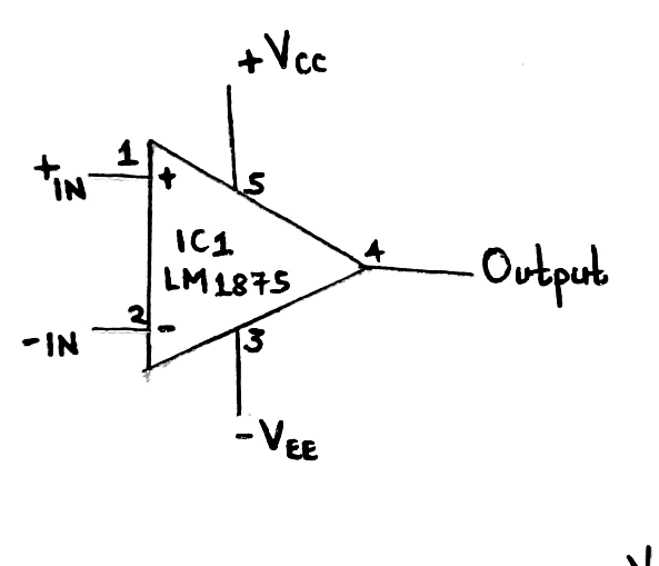
Pinout diagram of LM1875
LM1875 is a 5-pin amplifier. The pins are as follows;
Pin1/ Non-inverting input: It is the amplifier’s non-inverting end (+).
Pin2/ Inverting input: It is the amplifier’s inverting end (-).
Pin3/ Vee: It is the ground pin or negative supply voltage.
Pin4/ Output pin: It outputs an amplified signal.
Pin5/ Vss: It is the positive supply voltage pin.
The Features of LM1875
The specifications and outstanding features of LM1875 are listed below.
- It has a wide supply range (operating voltage) from 16V to 60V. Also, its maximum input offset voltage is 15mV at ±25V.
- Secondly, it has thermal protection alongside a parole circuit. Moreover, it has device overload protection against DC and AC short circuits to the ground.
- Also, it is breadboard-friendly and has a fast slew rate.
- Fourthly, it has a low harmonic distortion noise at the following values – 0.015%, 8 Ohms, 1KHz, and 20W.
- Its output current capability is 4A, while its output power with a 4Ω/8Ω speaker is 20 Watts (30W maximum).
- Its operating temperature ranges from 0°C to 70°C, and a maximum load resistance between 4 to 8 Ohm.
- Additionally, it has a wide power bandwidth of 70KHz and can have an open-loop gain (ripple rejection) of 90bB.
- Finally, you can find it in a 5-pin TO220 package.
A Sample Application Circuit for LM1875
Basic circuit
The first diagram is a simple IC LM1875 circuit. The amplifier has an internal compensation. Therefore, it can have stable gains of at least 10.
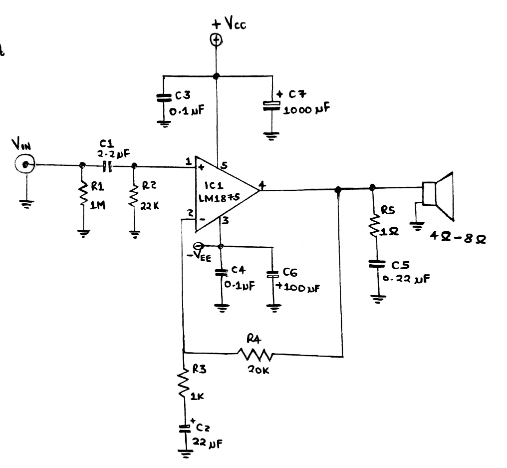
A primary circuit of LM1875 amplifier IC
25 watts OCL Audio Amplifier circuit
Our second application circuit generates an audio signal using a negative, positive, and ground power supply. Consequently, the movement possesses halves of both negative and positive signal swings. The final result is a crystal-clear output sound.
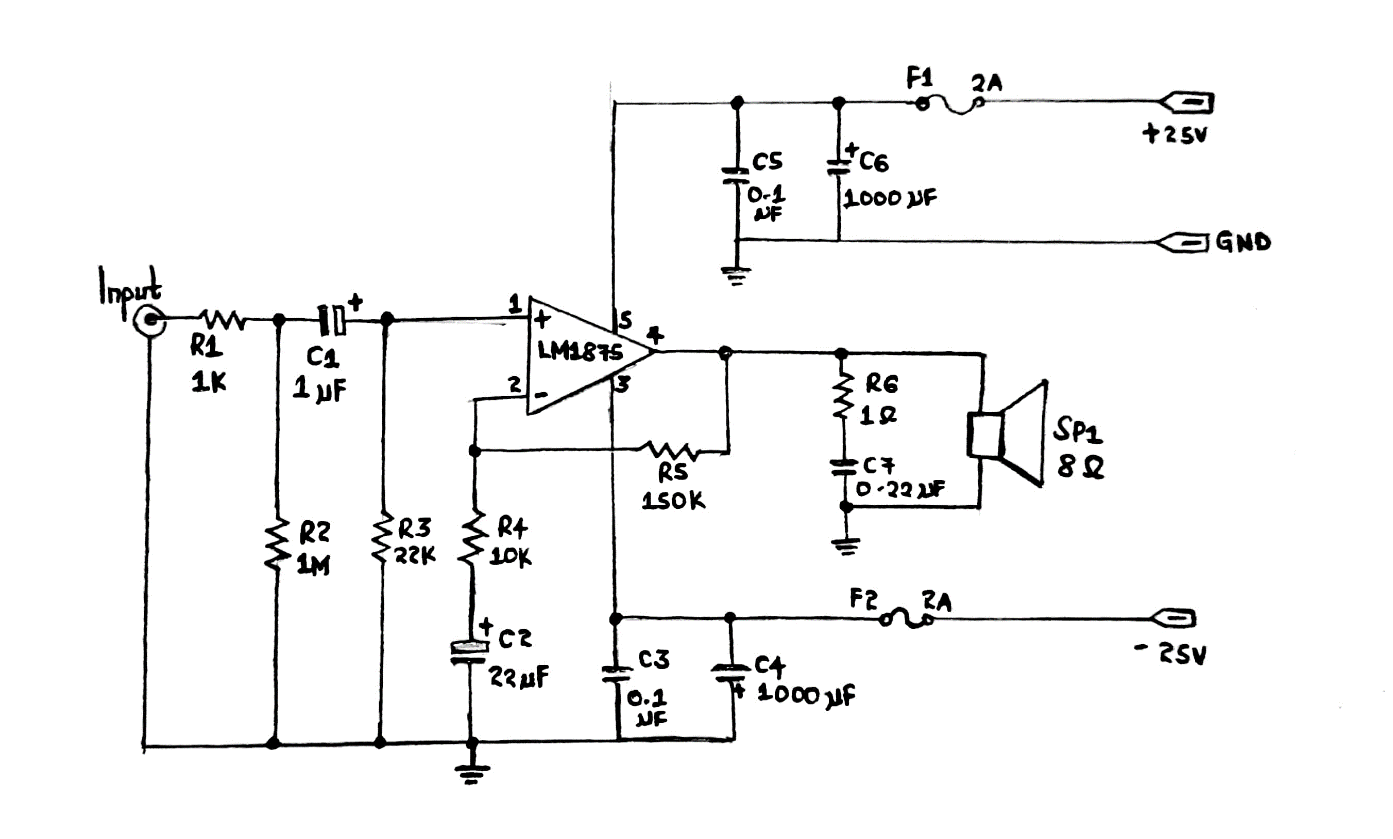
A 25W OCL audio amplifier circuit
Construction/ Working steps
- Start by applying a signal at the input pin. The limited audio signal will automatically flow through R3, C1, R2, and R2. Remember to reduce or eliminate the noise to the ground at that time.
- Afterward, we’ll have a non-return phase where the signal will proceed to input pin1 (non-inverting pin) of 1C1. Then, it’ll get to the speakers via output pin4.
- Thirdly, use R6 to limit the output signal noise to the ground. R5 allows the feedback of another part of the IC’s audio output from pin4 to pin2.
- You can also calculate the rate of boost-up using resistors R5 and R4 (about 15 times).
- Finally, C2 ensures the circuit gets better responses to high frequencies.
LM1875 OTL Amplifier circuit 30 watts
Our third and last project is suitable for a small-sized high-power amplifier. Besides being easy to construct, you only require a few electronic components.
The specific IC is LM1875T, which fits an amplifier model of a National Semiconductor.
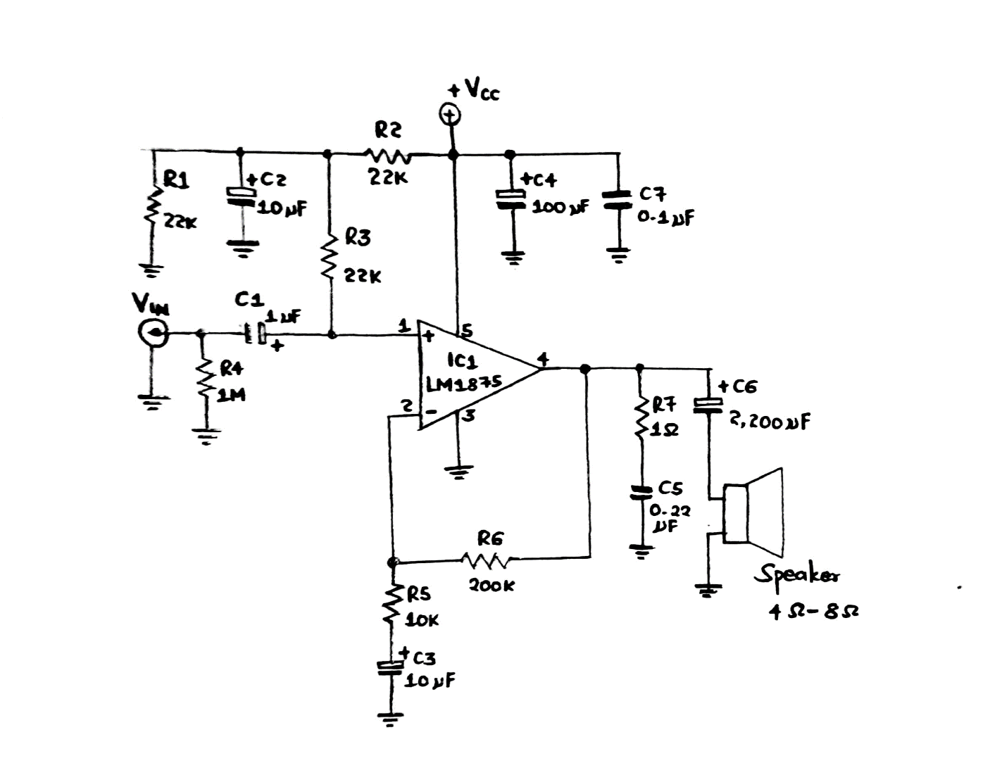
LM1875 OTL audio amplifier with 30 Watts
Circuit Explanation
- The DC power supply can range from 16V to 60V using both single and dual voltage. However, we’ll use it as the ground and positive since we have a single voltage supply.
- The power supply voltage will conversely affect the power IC. For instance, using a DC voltage supply of 50V causes a power of 25W at the IC.
- The impedance load should be 8 ohms since we have a power output of 30W and a voltage supply of 60V.
- Apart from the protection system in the IC, a heatsink is favorable because it’ll help dissipate excess heat.
- Then, we have resistor R4, which adjusts the input impedance. Also, it couples with capacitor C1 inside IC1 into the amplifier section. C2 functions as a noise filter, limiting noise getting through the input.
- R6 and R5 have a feedback form connection that adjusts the circuit’s gain.
- C5 and R7 bypass any high noise frequency heading to GND, improving the output sound quality. In addition, C6 couples signal to the load/output. In this way, there’s no or less DC voltage leak to load and better sound quality.
LM1875 Alternatives
LM1875 alternative is TDA2050.
You can also use other audio amplifiers like TDA7265, TDA2005, LM386, TDA7279, TDA1554, and TDA2030.
Applications
LM1875 audio amplifier is often used in the following applications;
- Cascading of audio speakers,

(audio speakers)
- Servo amplifiers,
- Instrument systems,

9an electric guitar
- Audio signal amplification,
- Stereo phonographs,
- Bridge amplifiers,
- High power amplification,
- Split/Dual power supply operation.
Conclusion
LM1875 IC is a low-frequency class AB amplifier often suitable for consumer audio applications. One of the LM1875 design features includes having internal output protection diodes. Furthermore, manufacturers achieve the quality performance of LM1875 IC by using advanced circuit techniques.
For more information on the LM1875 audio amplifier IC, kindly contact us.