Contents
What is LM311?
LM311 is a cost-effective voltage comparator commonly applicable in several comparison circuits like water leak detection and light control. It’s mostly in 8-pin packages.
LM311 Pin Configuration
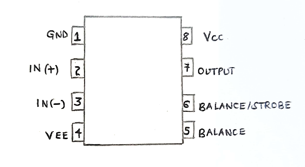
LM311 pinout
The LM311 has a total of eight pins, as we’ll discuss below;
Pin1/ Emit out / emitter output pin: It functions as the output’s transistor emitter pin.
Pin2/ Non-inverting input pin (IN+): It provides a variable voltage for comparison.
Pin3/ Inverting input (IN-): It receives a fixed voltage that you compare with the variable voltage.
Pin4/ Ground (VCC-): It connects to the system’s ground. Also, you can apply a negative voltage here.
Pin5/ Balance pin: It switches off the DC-offset voltage. It also requires a low input current at the offset and bias.
Pin6/ Strobe input / Balance: It switches off the output stage.
Pin7/ COL OUT/ Collector output pin: It operates as the transistor’s collector output.
Pin8/ VCC+: It provides an operating supply voltage of up to +15V to the Op-Amp.
LM311 IC Features / Technical Specifications
Some technical specifications and chip features of LM311 include;
- First, it has a wide power supply range. For instance, its dual supply ranges from ±2.5V to ±15V, while its single power supply ranges from 5V to 30V.
- Then, you can isolate its output and input from the system’s ground.
- Thirdly, it can operate most MOS and TTL loads since it has a low power consumption design.
- It can also drive loads of up to 50mA and 50V.
- It has strobe functionality and offset balance capability.
- In addition, it can provide a reliable operation through the single supply for the two op-amps.
- You can find it in 8-pin PDIP, 8-pin SOIC, 8-pin SO, and 8-pin TSSOP packages.
- Lastly, its maximum current from the VCC+ pin is 7.5 mA.
LM311 Equivalent ICS
Often, NTE922 and LT111A act as perfect equivalents of LM311. Also, you can use an alternative comparator Op-Amp IC like LM324, LM339, LM211, OP07, LM111, LM358, or LM741.
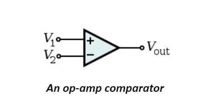
Where to use the LM311 Comparator Operational Amplifier?
Generally, the LM311 comparator Op-Amp helps electronic devices in voltage comparisons. Its advantage over other voltage comparators is including an output transistor in its package. Additionally, its hardware can control the emitter and collector of the transistor, thereby making it ideal for many applications.
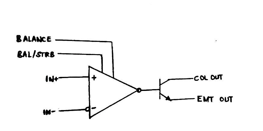
A simplified schematic diagram of LM311
As we’ve seen, its transistor can drive loads like MOS, RTL, and TTL loads of up to 50mA and 50V. You can use the transistor to isolate the load from the system ground.
How to use LM311 IC?
We will present some projects that use an LM311 IC voltage comparator.
Heat sensor using LM311 IC
Circuit diagram
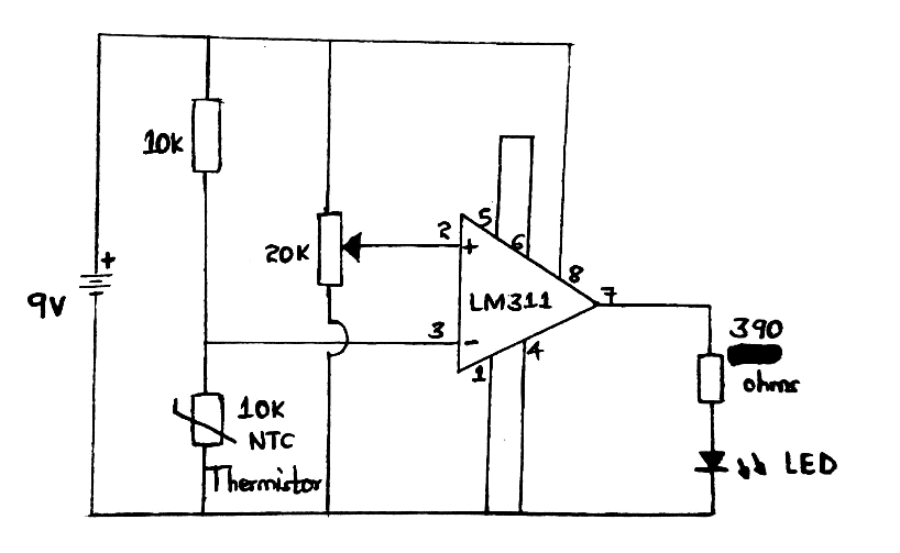
A basic circuit diagram of heat sensor using LM311 IC
Circuit explanation
- The LM311 is in comparator mode.
- Further, it has passive components such as a 10K (Negative Temperature Coefficient) NTC thermistor operating as a heat sensor.
- Then, the 20K variable resistor in the circuit sets the recommended heat level.
- The LED bulb acts as LM311 output.
- When the heat increases to its preset level around the thermistor, the LED lights up because of increased LM311 IC output.
LM311 Light controller circuit
Circuit diagram
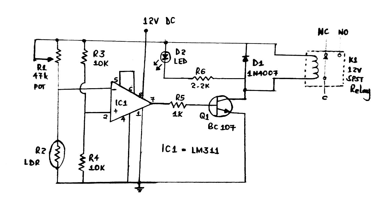
The Circuit diagram of the LM311 light controller
Circuit explanation and working
- There’s a voltage comparator IC, i.e., LM311.
- Then, we have resistors R4 and R3 situated at IC1’s non-inverting input, producing a 6V reference voltage.
- When there’s a low comparator output and high potential of the inverting input terminal, Q1 doesn’t turn on as expected. Then, the relay fails to work. The resistance occurs because the photoresistor resistance reaches more megaohms in darkness.
- Contrarily, a high comparator output and low inverting input terminal turn the Q1 on while driving the relay. At that time, the photoresistor resistance is approximately 5-10K. Adjusting the LM311 input +- results in an opposite outcome.
- Finally, if you adjust R1, you can set the level of illuminance to drive the relay.
Applications of LM311
They comprise;
- Oscillator electronic circuits,
- Automation projects,
- Power supplies,
- Electrical appliances,
(washing machine – type of electrical appliance)
- High voltage protection/warning,
- Peak voltage detector,
- Switching power amplifier,
- Free running mulltivibrator,
- Zero crossing detector,
- Driving motors, lamps, relays, etc., often under 50mA, and
- Voltage comparator circuits.
Conclusion
All in all, LM311 is a high-speed differential comparator used for logical operations that require comparing voltages. The article above has further shown you its features and how to apply them in projects. For more information, however, you can reach out to us.