Many voltage regulator components that integrate on an electronic circuit exist on the market today. Each of them provides voltage adjustment capabilities, but we will look at the LM317 pinout. Generally, this affordable device allows you to adjust the voltage via its adjustable pin. However, it requires two resistors to perform this task. It also contains essential features that make it applicable for high-powered electronics. Additionally, this device can supply a current rating of 1.5A over 37V.
Understanding this topic can seem quite confusing at first, and that’s why we put this article together. So let’s take a look!
Contents
1. What is lm317?
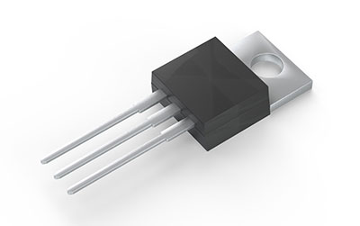
The LM317 component
LM317 serves as a three-terminal positive-voltage regulator. The component provides voltage adjustment capabilities and supplies up to 1.5A over 1.25V to 37V. Additionally, it only needs two resistors to configure the output voltage. What’s even more, the regulator contains 0.01% line regulation along with a 0.1% load regulation. It also features thermal overload protection, safe operating region protection, and current limiting. Furthermore, the overload protection will still operate when the adjusted terminal disconnects.
2. Pin Description of LM317 & Features
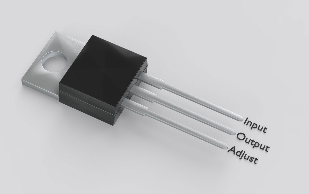
We detailed the LM317 pin description in the table below:
| PIN | Pin name | Description |
| 1 | Adjust | Output voltage adjustment pin. |
| 2 | Output voltage | The pin generally receives the regulated output voltage from the adjusted pin. |
| 3 | Input voltage | This pin receives the regulated input voltage. |
You can also take a look at the features below:
- 1.25V to 37V output adjustable voltage range
- Thermal overload protection
- Short circuit protection
- Overheat protection
- Low standby current
- Provides output current rating of 1.5A
- Affordable
- Reliability for commercial applications
- 40V DC maximum input voltage
3. LM317 Specifications

4. LM317 Alternatives
Some LM317 alternatives include the following:
- LM117
- LM217
- LM1086-ADJ
- LT1086-ADJ
- LT1117-ADJ
- B29150
- LM338
- LM1084-ADJ
- LM7805
- LM7806
- LM7809
- LM7812
- LM7905
- LM7912
- LM117V33
- XC6206P332MR
A few ICs provide varying pin configurations from LM317. It would help if you verified the pin configurations before circuit implementation.

5. LM317 Applications
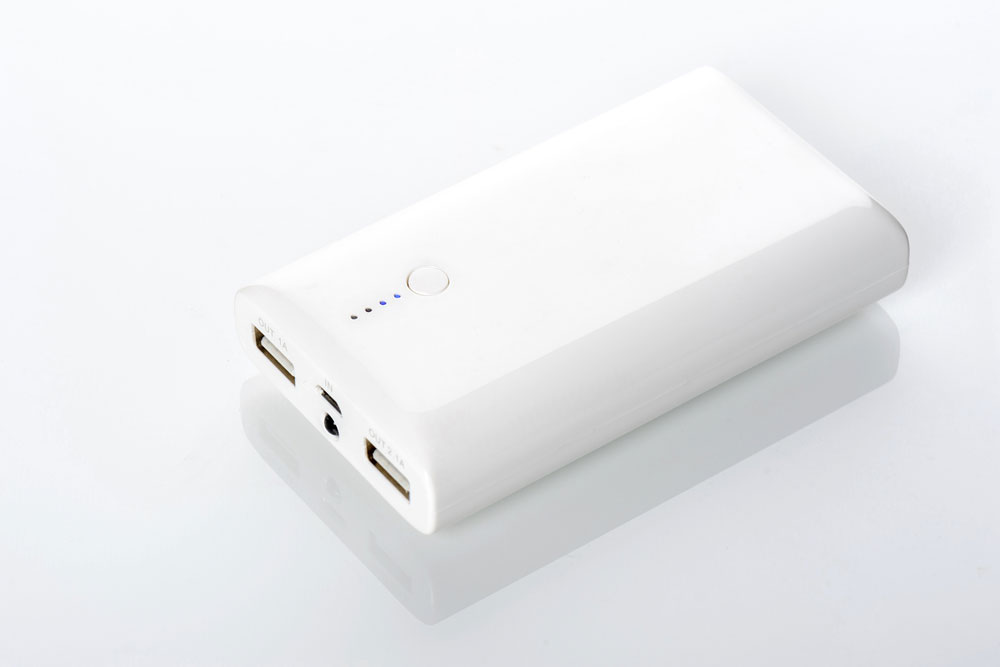
A power bank features an LM317 component.
The LM317 component has a wide range of applications, including:
- Voltage step-down circuits
- Ethernet switch
- Refrigerator
- RFID reader
- Washing machine
- Energy harvesters
- DVD player
- Desktop PC
- Battery charger
- Power bank
- DC to DC converter
- Current limiting circuit
- Positive voltage regulation
- Reverse polarity circuit
- Motor control circuit
- X rays
- Programmable Logic Controller
6. How to use LM317
This LM317 component forms and regulates 1.25V between both output and adjustment pins. You can alter the output with two resistors connected between the output and input pin. Additionally, two decoupling capacitors can connect to a circuit. This integration can eliminate unwanted coupling while preventing noise. Meanwhile, a 1µF capacitor connects to the output, boosting transient response. Then, you can make it serve as a variable regulator by clicking a potentiometer to the adjustable pin. The resistor and potentiometer work together, producing a potential difference that regulates the output.
7. LM317 resistor/voltage calculator

You will need to perform calculations for the voltage output value
You can calculate the output voltage (Vout) with the equation below. It relies on both external resistor values R1 and R2.

Although you can set the R1 value to 240 Ohms (recommended), it can also set between 100 to 1000 Ohms. Then, you must enter the R2 value to perform output voltage calculations. Use a 1000 Ohms value for R2 in this case. The above values complete the formula as shown below:

With the same formula, you can calculate the R2 value. You will need the output voltage value. So, if your output voltage sets to 10V, then you can calculate the R2 value with the below method:
10 = 1.25x(1 + R2/240)
=> R2 = 1680 Ohms
8. LM317 Circuits Examples
Take a look at three examples of an LM317 component on a circuit:
Variable DC Power Supply
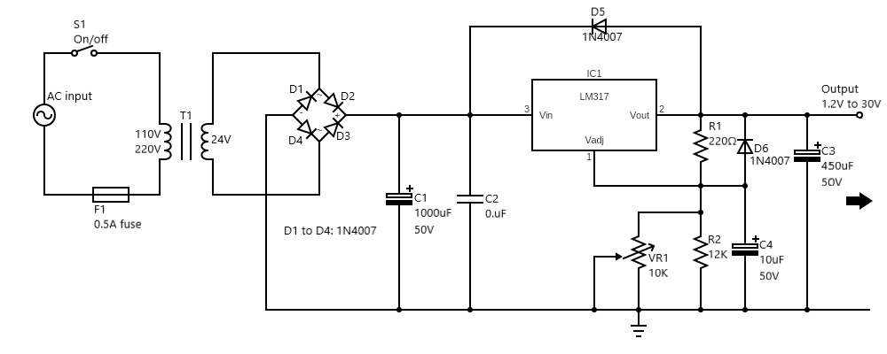
Circuit diagram of a variable DC power supply
This variable DC power supply generally allows a user to adjust voltage from 1.25V to 30V and 1A currents. In effect, this operates as a power supply rather than a 1.5V AA battery.
The transformer (T1) reduces the current from AC 220V to AC 24V. Afterward, it distributes to the bridge diode rectifier, D1 to D4. The C1 filter capacitor stores voltage rated at DC 35V. Meanwhile, the IC1’s adjustment pin adjusts the output voltage for the VR1. Then, the VR1 controls the DC voltage from 1.25V to 30V or 37 max at 1.5A.
USB Battery Replacement
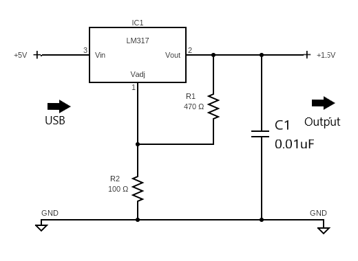
USB battery replacement circuit diagram
You can also use this USB battery replacement circuit as a power supply, and it generally reduces the 5V input voltage (USB port) to 1.5V/1.5A maximum output. The entire process occurs through an LM317 DC voltage regulator, and it will also perform well with 3V results. Additionally, this circuit features two resistors that adjust the LM317’s output voltage via the adjust pin. One resistor (R1) has a rating of 470 Ohms, and the second resistor (R2) has a 100 Ohms rating.
Overall, this circuit serves as a battery replacement to power USB-compatible electronics. For example, you can plug a music player into it to listen to some tunes if the battery dies.
Nicad Battery Charger using LM317T
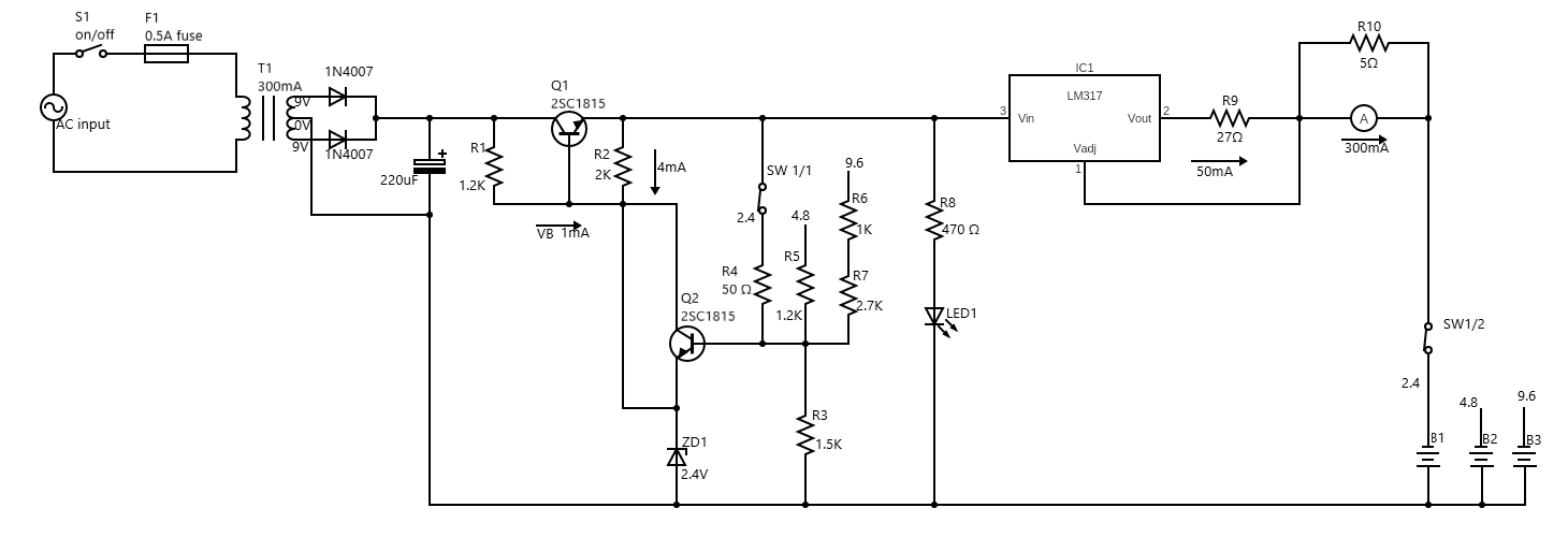
NiCAD battery charger circuit diagram with the LM317
This circuit allows you to charge a 2.4V, 4.8V, and 9.6V NiCD battery. The transformer’s secondary winding sets to 9V/300mA. Meanwhile, the 220uF 25V capacitor serves as a filter to smooth the voltage. A regulated circuit adjusts the voltage in each of the battery levels.
Also, the circuit features a LED to determine when it activates. The R8 resistor restricts LED1’s current. Additionally, an ammeter connects to the course to determine the battery’s charging status. At first, it will display a high wind. But when the battery charges, it shows zero. The SW1 component allows you to select the voltage that charges the battery.
Summary
Overall, the LM317 presents many practical applications on circuits. It provides the ability to supply a current of 1.5A over 1.25V to 37V. Not only that, but it requires two appropriately rated external resistors to set the output voltage. With that in mind, this component also features three pins, including the input, output, and adjustable buckle. Each pin provides unique characteristics. For example, the input pin receives regulated input voltage. Meanwhile, the adjustment pin changes the voltage and distributes it to the output pin. This entire process makes it useful for voltage regulation.
Do you have any questions regarding the LM317 component? Feel free to contact us!


