What is lm393?
LM393 is an integrated circuit with two internally inbuilt operational amplifiers that use a single power supply to perform different tasks.
Additionally, they can also apply a split power supply in their work, and it’s a dual-package comparator IC.
- lm393 Pinout Configuration
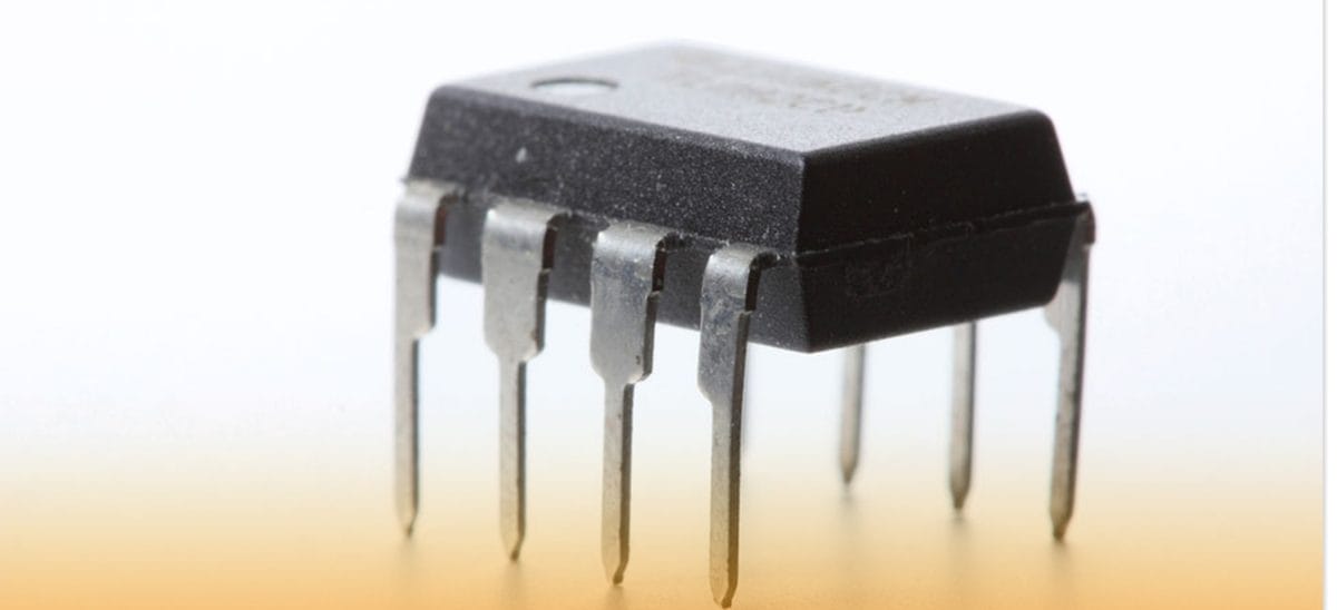
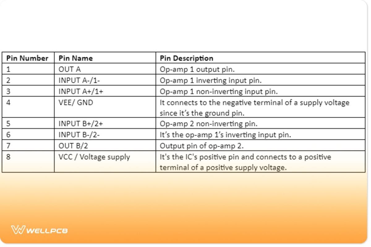
An IC LM393 comparator has a total of two independent voltage comparators in its single 8-pin package.
So, the table below will further explain its pinout and the functions of each pin in the 8-pin package.
lm393 Features and Specifications
The features of LM393 IC have the following parameters and values;
- Single voltage supply – 2V to 36V,
- Differential i/p voltage – 36V,
- Package – DIP and SOIC 8 pin,
- Drain current – 0.4mA,
- Storage temperature – -65°C/W to 150°C/W,
- Lead temperature – 260°C,
- Power dissipation – 660mW,
- Split supply – ±1V to ±18V, and
- Input offset voltage.
How to use LM393
Let’s use an example whereby the IC LM393 receives a +5V supply voltage circuit.
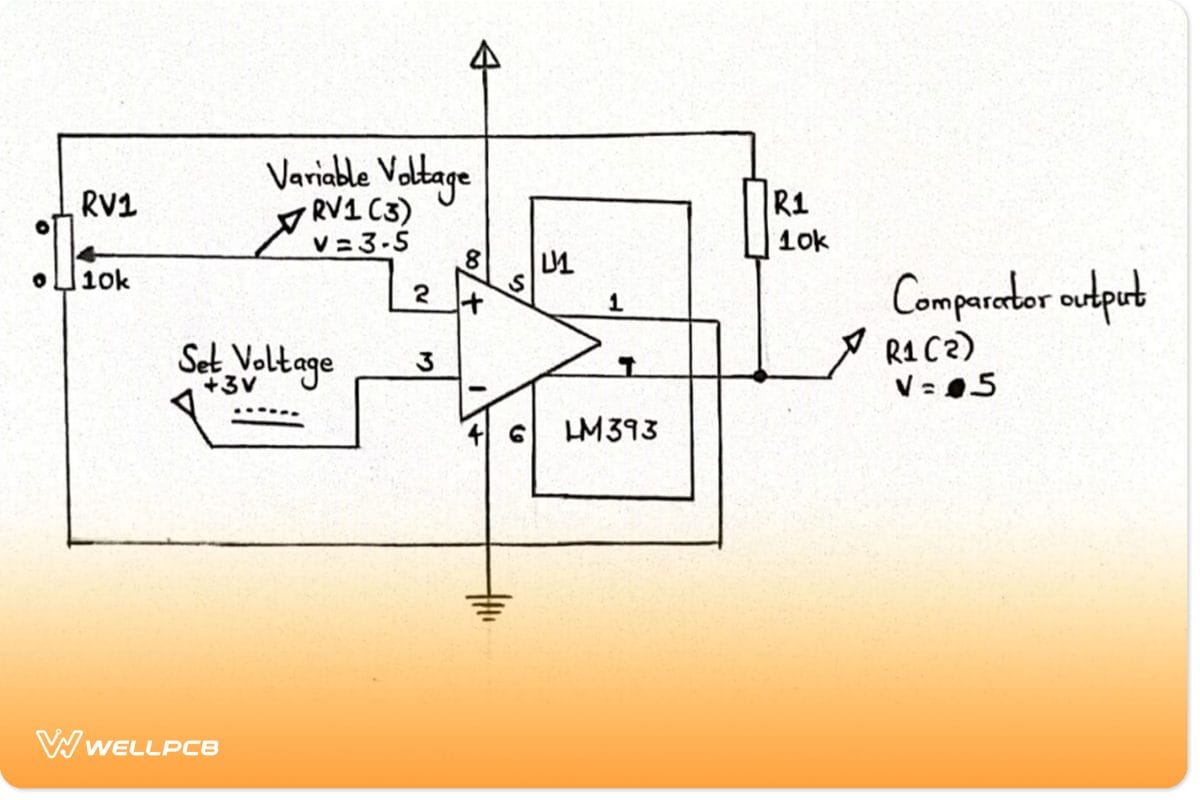
Circuit diagram with +5V power supply
- Here, pin8 (the voltage supply pin) connects to the +5V supply voltage. Then, pin4 remains grounded to keep the circuit at 0V potential.
- The sample circuit below shows a high output voltage when pin7 has a lesser voltage than pin2. Furthermore, a potentiometer varies the non-inverting terminal voltage while the inverting terminal voltage is 2.5V.
- Then, Pin6 and pin5 help in balancing the voltage in case there’s a need to adjust the DC-Offset voltage manually. Under normal circumstances, they may be inactive and shorted since the Input Offset current has better control.
- Lastly, we have a grounded pin1 and a transistor’s pin7 (collector pin) that achieves the output. The two pins contribute to a circuit design called a collector output circuit.
Note
You can use its equivalents or alternatives if you can’t help an IC LM393. For example, we have LM358, LM311, LM741, LM193, TL082, LM339, LM293, and LM2903.
- LM393 IC-based Automatic Night Light Circuit
In this lm393 IC-based night light circuit, we’ll start with the voltage comparator principle. We’ll also get a photoresistor that often controls a voltage divider circuit.
Components list
- IC LM393,
- Potentiometer (ranging from 1KΩ – 20KΩ),
- LED,
- Resistors – 330Ω and 33Ω (can be any value that approximates the mentioned values),
- DC power supply or 3 ‘AA’ batteries,
- Light sensor/photoresistor.
Circuit diagram

Automatic night light circuit using LM393 IC
Circuit working explained
First, we must understand that LM393 IC has two power inputs, GND and Vcc. GND is the ground wire of the voltage source, while Vcc is the positive voltage supply reaching approximately 36V.
The two power terminals complete a power lane and enable the circuit operation.
The operational amplifier ICs work separately and produce independent outcomes in a typical situation. 6 The LM393 IC comprises two internal op-amps, each containing two outputs and inputs.
(operational amplifier).
But in this case, one op-amp will have no connection since IC LM393 uses only one op-amp.
Also, the circuit here only checks one voltage/current level. Therefore, one op-amp is ideal.
Steps to consider
- After applying power to the IC, compare the voltage values. A higher inverting terminal voltage than a lower non-inverting voltage causes the op-amp output to fall to the ground. Because of that, the current flows from the positive supply to GND.
- Conversely, a higher non-inverting voltage maintains the output of op-amp output at Vcc (positive power supply voltage). Subsequently, there’s no current flow since no potential differs across the load.
- A high voltage at the inverting terminal turns ON the load (LED). Conversely, a low voltage at the inverting terminal turns OFF the LED.
- The circuit uses a photoresistor for light detection instead of the LED as load. The photoresistor’s resistance depends on the light hitting its surface. That is, its resistance decreases when exposed to bright light and increases when exposed to darkness.
- So, we can connect a voltage divider circuit with a fixed resistor and photoresistor. If the photoresistor detects darkness, it’ll use more voltage because of less resistance. However, in bright light, increased resistance results in low voltage use.
- Finally, we’ll have a comparator circuit that ensures the LED is ON during darkness and remains OFF in bright light. Briefly, the input of non-inverting terminal voltage can act as the reference voltage. The reference voltage becomes lower than the photoresistor voltage in darkness and vice versa in light.

(automatic night light).
lm393 Application
You’ll find the LM393 IC in a wide variety of applications like:
- Peak voltage detector,
- Battery-powered applications,
- Time-delay generators,
- Analog to digital converters (ADC),
- Oscillator circuits,
- Logic system applications,
- It can also drive motors, relays, lamps, etc.,

(street lamp)
- Voltage comparator circuits,
- High voltage protection or warning and
- Zero crossing detector.
Conclusion
The LM393 IC is a single-supply, double, low-power, low-offset voltage, and differential voltage comparator.
It is currently widely applicable in automotive, You’llrial, or educational applications, among others.
Still have questions?
Don’t worry —our team of professionals is ready to help if you contact us.