High dynamic signals will always pose a problem to designers. They are necessary for echo-ranging devices such as radar or sonar systems. But in such systems, we need high gain for the low amplitude signals and vice versa for high amplitude systems. Also, another problem with the signs is that they require scaling. The process is imperative in limiting input signal loss and clipping at either end of the amplitude range. A log amplifier is pertinent in solving this problem. Our article will explore deeper. Let’s get started!
Contents
What is a Log Amplifier?
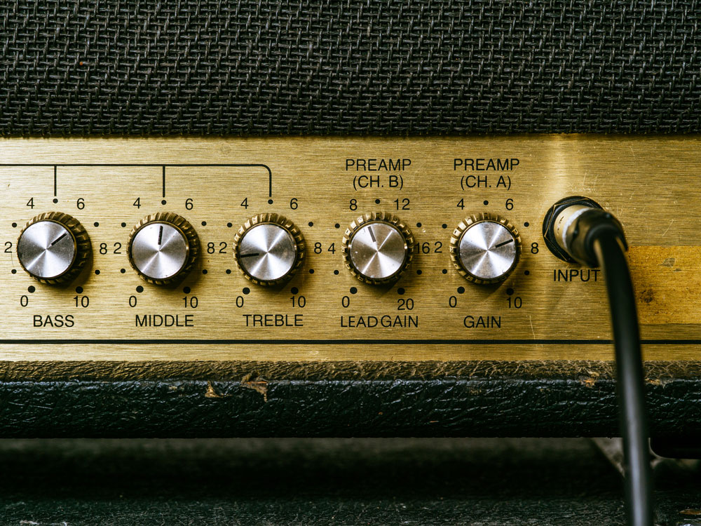
Figure 1: A Conventional Amplifier
It is an operational amplifier that operates as a logarithmic converter. Nevertheless, unlike others, its output voltage is directly proportional to the natural log of the actual input voltage.
Hence, in logarithmic amplifiers, multiplying the input voltage natural log with a constant value gives an output.
The Working Principle of Log Amplifier
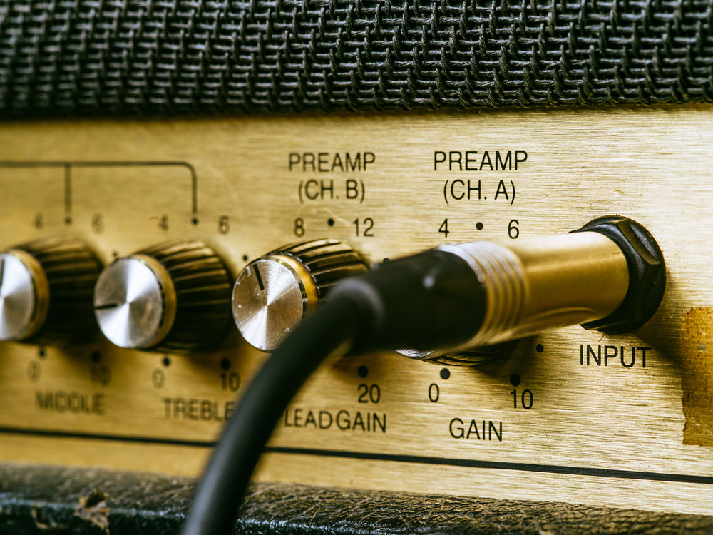
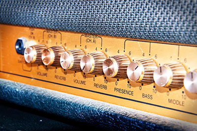
Figure 2: Vintage amplifier knobs and input
The following logarithmic function describes the working principle of logarithm amplifiers:

In the equation, K represents the constant. On the other hand, Vref represents the normalization constant.
During operation, the logarithm amplifiers require more than a single operational amplifier. In such a case, the additional amplifiers are called compensated logarithm amplifiers.
In addition, they require other external components such as high-performing op-amps like LM771, LM714, and LM1458.
The diode in the log amplifier is in a forward biasing mode. Therefore, the diode equation of the amplifier is
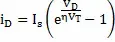
It represents the saturation current, VD represents the diode’s voltage drop, and VT is the thermal voltage. It is also possible to rewrite the diode current in a high biasing state.

In this case,

Also, note that the voltage at the inverting terminal is at a virtual ground state. Therefore, output voltage equals -VD.
Moreover, note that i1 equals iD.
Hence,
The final equation of the voltage output (output signal) of the log amplifier is


Log Amplifier Topologies
Primarily, there exist two types of log amps. First, there is a multistage log amplifier and a DC log amplifier.
The multistage log amp
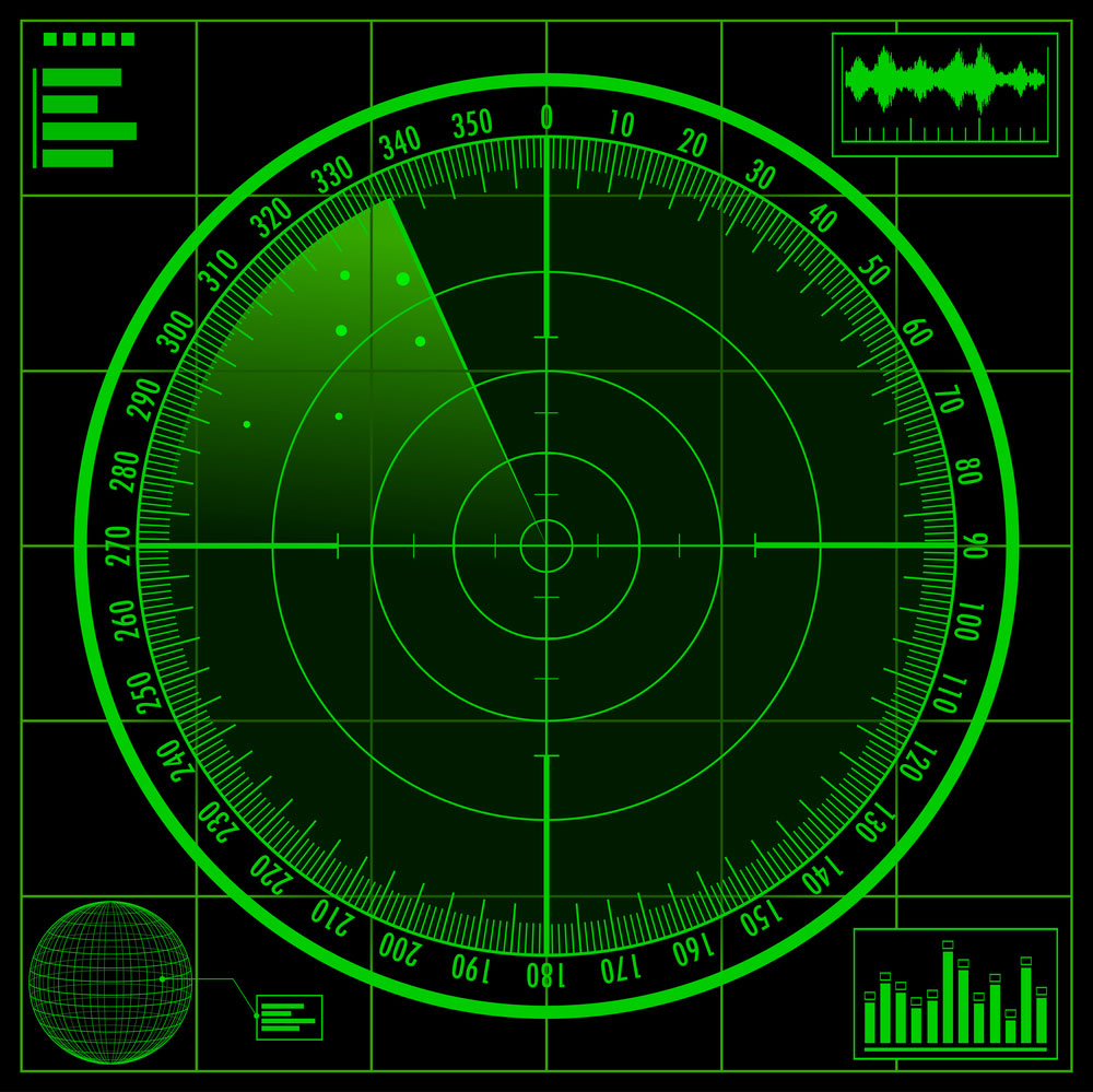
Figure 3: A Radar Screen
Its working relies on sequential limiting in a set of amplifiers in series connection. You’ll find this sort of topology in high-frequency signals, and therefore the topology is shared in a wide range of applications such as communication systems and radar devices.
When you connect multistage log amps, as shown below, you will get a logarithmic amplitude response. Also noteworthy is that the series of amplifiers feature overload limiting characteristics.
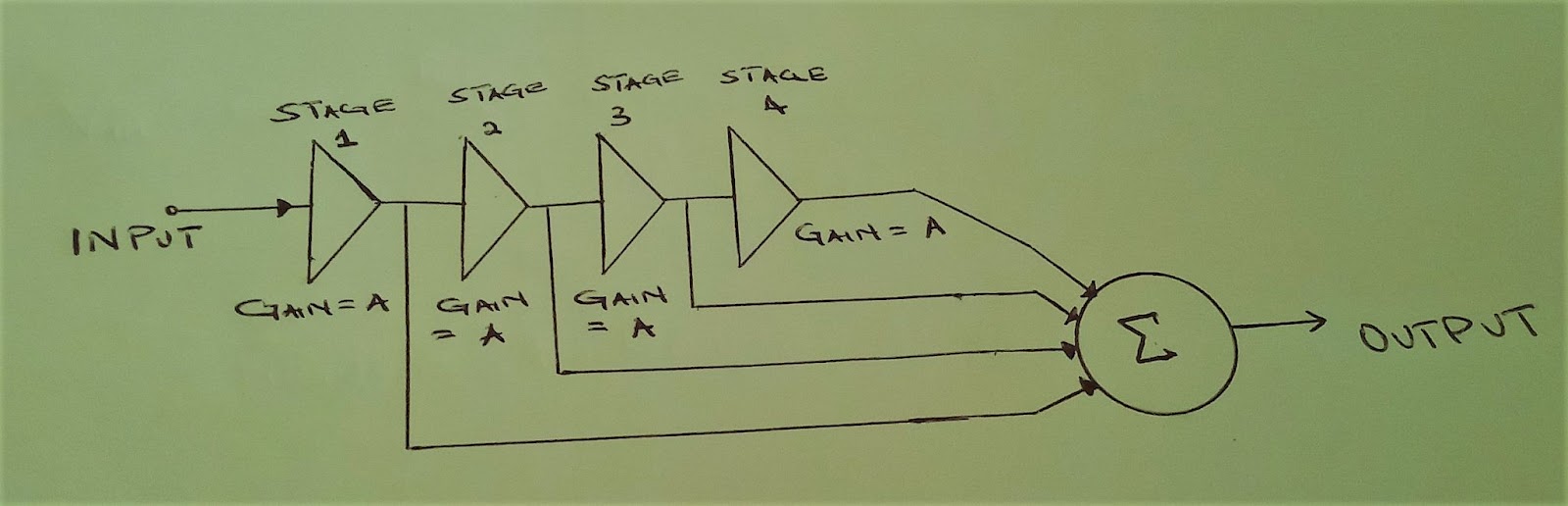
Figure 4: A Multistage log amp connection.
While this topology helps generate a logarithmic response, it is not immune to propagation delay, and the problem is present at every amplifier stage.
The cause is that a signal component from the initial stage will get to the summing circuit first. Ideally, the signals from the other locations should arrive first. The result is a distortion of the output waveform.
Altering the primary log circuit of the amplifier chain will solve this issue. Instead of the single-stage amplifiers, you can replace them with pairs of amplifiers. In the new amplifier configuration, the former problem is no longer present.
The DC log amplifier
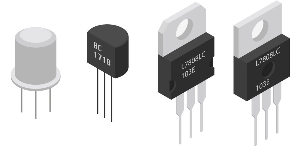
Figure 5: Isometric Electronic components Transistors
It is the alternative log amp topology of the type above. There is a diode in the op-amp’s feedback path in this amplifier string. You’ll find a diode-connected transistor in place of a diode in some.
The op-amp output at the transistor base-emitter junction will be proportional to the log amplifier current at the input level. Also, the output voltage in this configuration equals the log of the following ratio- input current: emitter saturation current.
Like the other circuit, this also has a limitation because it has a temperature-dependent output. You can solve the temperature dependence problem by connecting two amplifiers as a differential pair. Also, an additional temperature monitoring circuit will significantly guarantee a maximal response.
Log Amplifier Circuit
Opamp-diode log amplifier
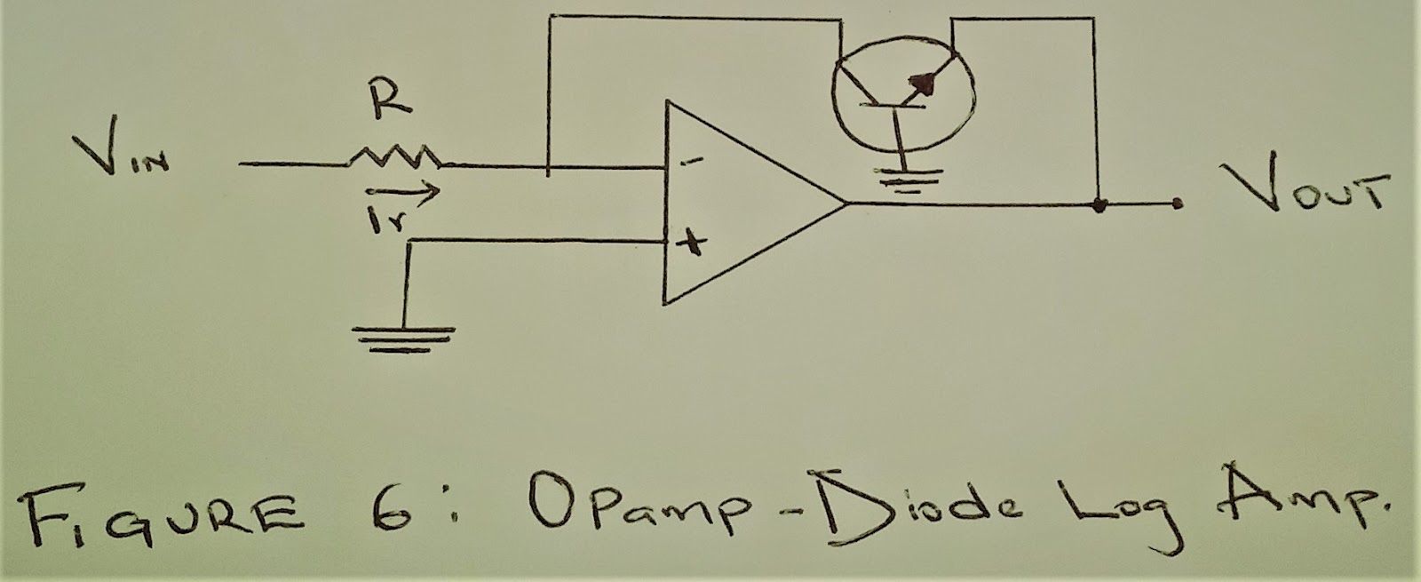
The op-amp, in this case, features a diode in the feedback path in a closed-loop inverting configuration. Note that the voltage across the diode will be proportional to the log of current that passes through.
On the other hand, when the op-amp is in a noninverting mode, the output voltage is proportional to the -log of the input current. Also, note that input voltage is proportional to the input current, and thus, the output voltage is proportional to the negative log of the input voltage.
Opamp-transistor log amplifier
Here is a circuit diagram for this type of amplifier.

For this kind of amplifier, there’s a bipolar junction transistor on the feedback path of the op-amp in an inverting mode. Note, in such electronic circuits, you’ll need to connect the transistor’s collector to the inverting input.
Also, connect the emitter to the output and finally ground the base.
For this op-amp to operate, you must ensure that the input voltage is positive.
Applications of the logarithmic amplifier
A logarithmic converter is helpful in the following:
Figure 8: Audio effects processors in a rack.
- Useful in mathematical operations that involve multiplication.
- In addition to multiplication operations, it is useful in exponential functions and division.
- They are useful in analog computers for synthesizing audio effects.
- Useful in an analog-to-digital converter.
- Also essential in measuring instruments that require a multiplication operation.
- Log amplifiers are essential in calculating decibel (dB).
- Monolithic logarithmic amplifiers are essential in radio frequency domain operations.
- Useful in converters such as analog-to-digital converters and root mean square converters.
- Essential in comparator applications.
- Lastly, they are useful in AC and DC signal amplification.
Conclusion
In the circuit design of most electronic components, log amplifiers are helpful. We have highlighted all there is to know about the element. Also, where necessary, we have included a functional block diagram. They are vital in guiding you to comprehend the connections involving the amplifiers.
Thus, the above insights should be paramount in enabling you to achieve maximum component operability. If you have further questions on its working and calibration process, talk to us, and we’ll promptly respond to your queries.


