Digital systems are at the peak of human technology. Such systems usually contain a microcontroller or computer that stores, processes, and communicates information in digital form.
But that’s the surface of it all.
Digital circuits exchange information in binary digit form, 1s and 0s. Plus, logic gates lay the foundation that created the mass of digital logic circuits we have today.
However, if you want a deeper understanding of a basic logic gate truth table, you must be familiar with Boolean logic.
Luckily, we wrote this article to tell you everything about logic gates, binary inputs, logical operations, and input combinations.
So, buckle up, and let’s begin!
Contents
What is Logic Gate and Truth Table?
In the digital world, a logic XOR gate is a set of transistors that work together to handle standard Boolean functions.
Plus, it’s a tool, which produces a single output level while combining the input levels. Thus, logic 1 means high, while logic 0 means low.
With the different blends of binary output mathematical functions, you can fully realize the shape of a digital system.
How Does it Work?
Various computers can carry out complex operations because of the interrelation of a digital logic gate.
Manufacturers implement basic gates through molecules, transistors, optics, diodes, and relays. Even by different mechanical elements. For this reason, you can think of logic gates as electronic circuits.
You can build logic gates in different forms like small-scale integrated circuits (SSI), very large-scale integrated circuits (VLSI), and large-scale integrated circuits (LSI).
Also, you can access the outputs and inputs of all gates of your integrated electronic devices, as well as the outer connections—similar to individual logic gates.
Truth Table
A truth table contains the different combinations of input variables. It also shows the matching output variables.
Furthermore, the truth table explains how the gate output of the logic circuit responds to different input logic levels.
On this table, the voltage levels are logic 1 and logic 0. Plus, we’ve two levels of logic which are negative logic and positive logic.
Logic High and Logic Low
All inputs and outputs of simple logic gates have two levels; ON and OFF, HIGH and LOW, TRUE OR FALSE, or 1 and 0.
For a positive logic system, the higher voltage level is 1, while the lower voltage level is 0.
However, in the negative logic system, the higher voltage level is 0, while the lower voltage level is 1.
But, when you consider the TTL (transistor-transistor logic), you can see the lower state as 0 volts and the higher state as five volts.
Types of Logic Gates
We’ve seven main types of gates you can combine to integrate all kinds of digital components. Let’s take a closer look at all the seven types of logic gates and how they operate.
AND Gate
The AND gate needs two or more inputs to operate and only produces a single output. The AND gate will produce a logic 1 output when all inputs are in a logic 1 state.
Likewise, it makes a logic 0 output when all inputs are in a logic 0 state.
The sign for representing AND operations is “.” or no symbol at all.
Furthermore, if you’ve X and Y inputs, the AND gate inputs can express the output as Z = XY. You can also call the AND gate types “all or nothing gate.”
Here are the logic symbols and truth tables of three-input and two-input AND gates.
Truth Table


Additionally, you can realize discrete AND gates by making use of transistors or diodes.
You can represent the X and Y inputs as 0V or +5V accordingly. Also, Z represents the output.
For the AND gate’s diodes, if both inputs have the same value, X = +5V and Y = +5V, the diodes will be in OFF condition.
For this reason, the current won’t flow via the resistor. Thus, there will be no voltage drop. So, the output is Z=+5V.
Likewise, if both inputs are = 0v, the parallel diodes will be in ON condition. Thus, the diodes will behave like short circuits. Also, the output matches the 0V.
Logic Gate Truth Tables– OR Gate
Like the AND individual gate, the OR gate has two or more inputs and produces a single output.
However, the OR gate will produce a logic 1 output if one of its inputs is in logic 1 state. Similarly, it will produce a logic 0 output if one of its inputs is in logic 0 state.
In other words, an OR gate is a single device that gives 1 as its output as long as one of its inputs is one. The sign used to represent it is “+.”
So, if we’ve X and Y as inputs, you can represent the output as Z=X+Y. Also, you can call the OR gate the “any or all gate.”
Here are the logic gate symbols and truth tables for three-input and two-input OR gates:
Truth Table

Truth Table

Additionally, you can realize discrete OR gates by using transistors or diodes. The X and Y inputs are either 0v or +5V accordingly. Also, Z represents the output.
Both diodes will be in OFF condition if both inputs have the same value, X=0V and Y=0V. Thus, stopping current from flowing via the resistor. Since there is no voltage drop, the output is Z = 0V.
Also, if both, or any inputs = +5V, the parallel diodes will be in ON condition and work like short circuits.

Logic Gate Truth Tables– NOT GATE
The NOT gate turns its inputs to its opposite. For this reason, we can also call it the inverter. The NOT gate has only a single input and one parallel output.
The output of this device is always the supplement of the input. So, if we have a logic 0 input, the NOT gate will produce a logic 1 output and vice versa.
The “-“ symbol represents the NOT operation. You can read the NOT operation as Z = X bar when ‘X’ represents the input variable and ‘Z’ represents the output variable; you can read the NOT operation as Z = X bar.
Here’s the logic symbol and truth table of the NOT gate:
Truth Table

The X-represented inputs are either 0V or +5V. Z will also represent the output. Thus, when the input X equals 0V, the transistor (Q1) gets reverse biased and will remain OFF.
For this reason, the current will not flow via the resistor. Since there’s no voltage drop, the output current (Z) matches the +5V.
Logic Gate Truth Tables– NAND Gate
The NAND gate is the first universal gate. Universal gates can single-handedly realize logic circuits.
This gate can carry out three primary logic-level functions—AND, OR, and NOT. Additionally, the NAND gate is a fusion of the NOT and AND gates.
The symbol “—” expresses the NAND operations. The NAND gate will produce a logic 0 output only if each input has a logic 1 level.
Here is the symbol and truth table of the two-input NAND gate:
Truth Table

When input X and Y of the discrete NAND gate equals +5V, both diodes will be in OFF state. Also, the transistor (Q1) will get enough base drive from the resistor’s supply. Thus the transistor will be ON, and the output matches the 0V.
Logic Gate Truth Tables– NOR Gate
NOR stands for NOT OR, which makes the NOR gate a NOT gate and OR gate combination. The NOR gate is the second universal gate. Here, the NOR gate will only produce a logic 1 level output at a logic 0 level.
Also, for other combinations of inputs, the output remains at logic 0 level. Here is the symbol and truth table of the NOR gate:
Truth Table

Two input AND gate The X and Y represented inputs may be 0V. Thus, the transistors Q1 and Q2 remain OFF. For this reason, no voltage flows via the resistor. Since there won’t be a voltage drop, the output current (Z) matches the +5V.
However, if any of the inputs equals +5V, or both inputs match the 5V, the similar transistors stay ON. Thus, the output current relates to the ground and = 0V.
Logic Gate Truth Tables– Exclusive-OR Gate
The Ex-OR gate is a logic circuit with two inputs and a single output. It takes the logic 1 state if either of its two inputs takes the logic 1 state or if both inputs are in logic one state.
Also, the output takes a logic 0 state. You can use the Ex-OR gate like an inverter. And to do this, you’ve to connect one input terminal to logic 1.
Here is the symbol and truth table:
Truth Table
Logic Gate Truth Tables–Exclusive-NOR GATE
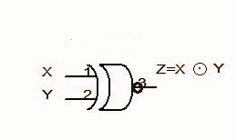
The X-NOR gate is the fusion of the X-OR and NOT gate. It also has a two-input and a single output concept.
The X-NOR will have a logic 1 output when both inputs are at logic 0 or logic 1. the output would be logic 0 if one part of the input is 1 while the other is 0.
Also, you can call this gate the coincidence gate. Why? Simple! It only produces output (1) if the inputs match.
You can also use this gate as an inverter by joining two input terminals to logic 0.
Here’s the symbol:
Wrapping up
Millions of logic gates each have their unique application. The AND gate works as an enabling gate that allows data to process through a channel. Also, the OR gate helps to detect more than one event in a circuit.
The NOT type of gate works like an inverter in most circuits, while the NAND gate has universal use in almost all circuits. The NOR gate is also universal, and the XOR and XNOR gate rates arithmetic operations and helps in parity detection and encryption in circuits, respectively. Well, that wraps up this article. If you have any questions, feel free to reach us, and we’ll be happy to help.