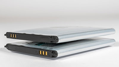
If you can care for and use your rechargeable batteries correctly, they can last for at least two years. Thus, taking care of your rechargeable batteries means you avoid charging your device in fast mode. Or better still, ensuring that the batteries don’t completely discharge. But if you choose to let your battery discharge fully regularly, it would take long before it permanently runs out of juice. Hence, the best approach is to recharge your battery when necessary. How? It’s simple. All you need to do is use a low voltage cutoff circuit. The device is effective for removing the battery from the load. And it also measures the battery’s voltage automatically.
Interestingly, we’ll extensively discuss how you could build one, the applications, and more.
So, if you’re ready, let’s begin!
Contents
What is a Low Voltage Cutoff?
A low voltage cutoff is a device that uses its circuit to turn off the load that connects to a battery automatically. Consequently, this helps to ensure the battery’s longevity.
The Theory of The Low Voltage Cutoff
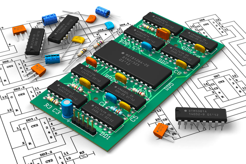
digital circuit board
A MOSFET transistor poses as the heart of the low voltage cutoff. And the transistor works like a switch in the external circuitry’s positive line.
So, by applying a low voltage cutoff for a circuit, you’ll be permitting a common negative ground among the load and battery of your device. Consequently, it’s helpful for a wide range of applications, like AC electric circuits, etc.
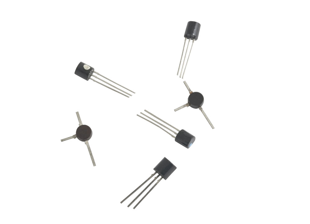
Transistors
But if you prefer a high cutoff switching, ensure to use a supply voltage that is less than your produced gate drive voltage. And you can get this by using a voltage-tripler circuit. An excellent example of this is the Op-Amp. As a result, your device will create about 5Khz square waves.
But that’s not all.
Also, you can feed the voltage more triple into the ladder circuit of the capacitor/diode. Then, the signal helps to gate on the MOSFET. As a result, it will increase the voltage to three times the square wave’s peak cutoff voltage.
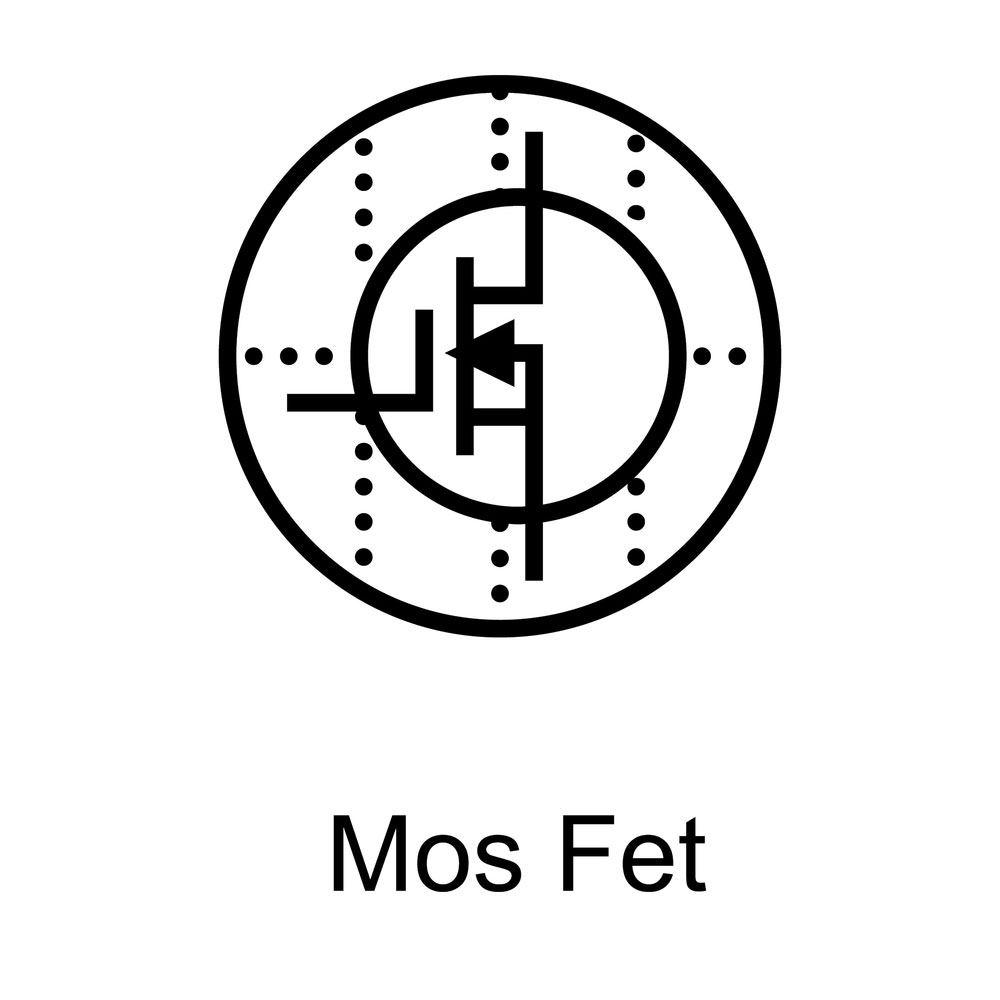
Mosfet symbol
So, when the low cutoff voltage shuts off, one of the resistors discharges the gate electric charge circuit. Afterward, the MOSFET goes off.
Three Voltage Comparators of a Low Voltage Cutoff Circuit
The low voltage cutoff circuit has a voltage comparator that comprises of:
- A standard 5-volt regulator
- Trimmer pot
- Dual op-amp
The low voltage cutoff circuit comes with a trimmer pot as a voltage divider. This action helps to protect your battery device from damage. And it’s responsible for creating a certain point where the low voltage shuts off.
That said, the op-amp, located in the low voltage cutoff circuit, also plays a vital role. It gives a positive output when the standard battery voltage is above the threshold. That way, you can avoid overcharging the device battery.
Hence, the positive output battery power creates a bias level through the voltage divider. As a result, the op-amp’s oscillator runs with a minimum voltage and reduces the battery charger.
The Operation Stage
The op-amp’s output usually moves to zero once the battery voltage goes below a certain point. As a result, the oscillator will shut off. Also, the MOSFET and voltage-tripler will shut down. Then, the resistor circuits some hysteresis. And this helps to avoid comparator oscillation close to the shutoff voltage.
The diode isn’t left out as it helps to shut off the circuit’s power when the MOSFET goes off. But, when the course comes on, the capacitor behaves like a brief short-circuit. Hence, it drags the op-amp Vcc line to the battery controller voltage. As a result, the entire circuit fires up until the MOSFET comes on. Then, the direct operating current passes through the MOSFET and diode.
What Happens When the Low Voltage Cutoff Switch Goes Off?
When this happens, the comparator forcefully goes off. And it occurs by shorting pin 3 to the ground. As a result, the MOSFET goes off. When the trimmer pot sets to Vcc, the resistor stops the switch from shorting the Vcc directly to the measure common ground. Also, the capacitor discharges via the current limiting resistor and the other half of the button.
Further, the capacitor’s discharge helps the circuit start the next time the switch goes on. Hence, the diode guards the MOSFET against the harmful spikes that an inductive battery load or motor produces.
If your load isn’t constantly under a few amps, you can use a thermally conductive grease and heat sink on your MOSFET. Also, you can use momentary push buttons over the DPDT switch if you prefer separate on-off controls.
So, the “off” push button will connect between the ground and the op-amp. On the other hand, the “on” push button will click between the D6 cathode and Q1 drain. Also, it’s vital to note that you can’t use the DC electric circuits, capacitor (C11), and resistor (R8) with push buttons.

How to Build a Low-Voltage Cutoff Circuit
The components you need to build the low voltage cutoff circuit is:
- Resistors

- Transistor
- Diode D1N750
- Relay Switch
- 12 volts battery
- Potentiometer
- Thick wires
- Circuit board
- LM324
- White LEDs

- Ceramic disc capacitor
- Input and output connectors
It’s vital to note that all the resistors are 1/4 watt.
Steps
- Refer to the circuit diagram. Then, start your point-to-point wiring on your circuit board.
- Get your thinned bare wire and cover it with Teflon insulation. The idea behind using the Teflon insulation is that it doesn’t melt quickly, even with abuse.
- Use your thick wires for the part of your circuit that will carry current.
- Add your connectors to the set-up. Then, you can use it as a switch. But, if your battery goes below a specific value, the circuit will go off.
- When your battery gets fully charged again, you can switch your circuit off and back on.
That said, it’s crucial to note that this low voltage cutoff circuit works perfectly with a gel-cell battery and 12 V car tail light.
Important Points to Note
- Connect your light bulb to the load output terminal. And link the power supply to the battery input terminal.
- Ensure that your potentiometer sets at the midpoint. Also, your variable voltage should supply 13 Volts.
- If your light doesn’t come on when you turn on the circuit, move your potentiometer towards the ground. Then, turn off the circuit and turn it back on. You can repeat the process until it happens.
Application of the Low Voltage Cutoff Circuit
You can use the low voltage cutoff circuit in the following applications:
- Landscape lighting
- Thermostats
- Doorbells
- Home security lighting
Wrapping Up
Your NiCd and lead-acid batteries can last for a while as long as you operate them within the ideal discharge voltages and charge.
Also, it would help if you had a low voltage cutoff circuit to prevent extreme battery discharge. And a charge controller circuit enables you to avoid a battery overcharge. Hence, a combination of both courses will ensure that your battery works in a suitable range.
Have you used the LDV before? Or do you need help with getting the best one for your project? Please feel free to contact us.


