Contents
What Do the Ratings on a Capacitor Mean?
Fortunately, almost all capacitors have a label that shows their ratings. You will find two ratings that specify the limits and capacity in terms of voltage and capacitance.
V often represents voltage in Volts when it sets a limit for the voltage in which a capacitor will function normally.
You could think of voltage as the magnitude of current passing through your MFD capacitor. Similarly, you could also compare voltage to water pressure in a pipe.
Furthermore, the amount of water in this scenario represents the current. If the pressure increases, the flow outside the line also increases.
For a capacitor, a higher voltage rating means the current will flow much faster as a result. However, if you pass the voltage limit, the capacitor will blow and disintegrate.
The second rating is in microfarads or MFD. This parameter usually represents the amount of capacitance. In other words, it is a value that shows you how much storage capacity the capacitor has.
Therefore, if the microfarad rating is high, it means that the capacitor can store more electric energy.
Generally speaking, capacitor ratings are often within 5 MFD and 80 MFD.
Still, you will find that some capacitors represent this rating as µF to illustrate their capacity.

(A standard 8.2 MFD capacitor )
The Basic Capacitor Types
MFD capacitors work similarly to a battery. Their job is to store energy and later release it when needed. However, capacitors do this much faster, which is why they are generally the better option. When connected to a 60Hz source, a capacitor releases its energy 60 times each second.
The total energy they can release is, however, dependent on their capacitance. Likewise, the larger the capacitor is, the more power it will consume. There are two main classes of capacitors; Running and Starting capacitors. The difference is in their capacitance MFD range.
Let’s take a look at each one.
Run Capacitors
Run capacitors lie within 3-70 MFD. Consequently, their voltage limits are either 370V or 440V. These capacitors also have a specific design that allows them to run regularly.
For this reason, they draw power continuously, which is why they are an excellent choice for single-phase motors.
An MFD capacitor is vital in such a motor when it comes to energizing the secondary winding. In such a case, you must choose the right size of the capacitor.
On the other hand, failing to do so means that the motor will develop an uneven magnetic field.
Rotor speeds will also fluctuate at the specific points where the field is unbalanced.
As a result, there will be tremendous energy loss in addition to dips in performance. You might also find that the unit keeps overheating, which is bad for efficiency.

(A run capacitor )
Start Capacitors
Start capacitors often have a higher capacitance range. It often exceeds the 70 MFD limit for running capacitors. For this reason, the voltage ratings could either be 330V, 250V, or 125V. Single-phase motors use start capacitors to aid in improving the starting torque.
Furthermore, the design of a start MFD capacitor works to optimize for brief usage. As soon as the motor achieves the necessary torque, the capacitor eventually disconnects from the circuit.
This electronic disconnection is a result of potential relays. These relays work through voltage limits. Essentially, a specific voltage level triggers the start capacitor disconnection. As a result, high capacitor values are more desirable. The reason is that more energy will go into generating sufficient starting torque.

(A start capacitor)
Is There a Difference Between MFD and UF?
The electrical charge stored in an MFD capacitor is through parallel conducting plates with a dielectric between them. The capacitance in this case refers to the amount of charge that a capacitor can handle. A digital multimeter is a measurement instrument designed to determine different electrical parameters, including capacitance.
Some capacitors have their capacitance ratings in MFD, while others use up to show the same. The bottom line is, that capacitor ratings will always be in microfarads. If you are wondering whether MFD and uF represent the same thing, then you are right.
In this case, the “MFD” term means microfarads, more commonly expressed in physics as uF. But the confusion comes in when you consider the millifarad units that could also stand in as mfd. Millifarads are of a more excellent order than the microfarad units.
The older capacitor manufacturers often represent microfarads as MFD, which was the standard back then. Today, most manufacturers prefer to use uF to represent capacitance. It is, therefore, quite rare to find a capacitor rated in millifarads. For consistency, uF is now the accepted standard for representing capacitor ratings.

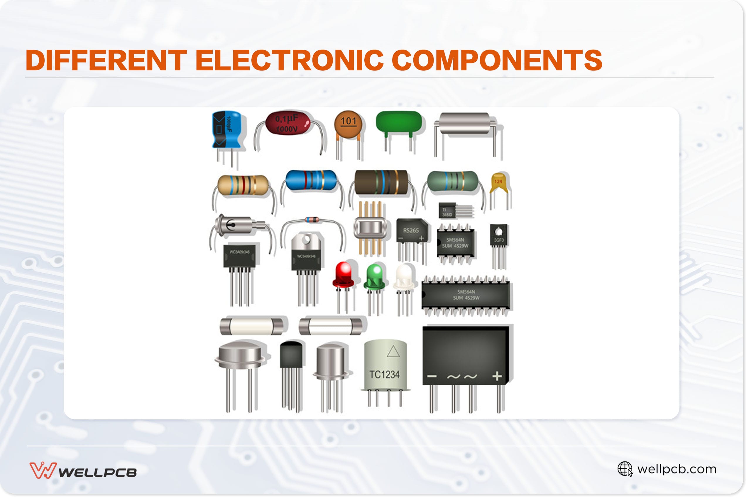
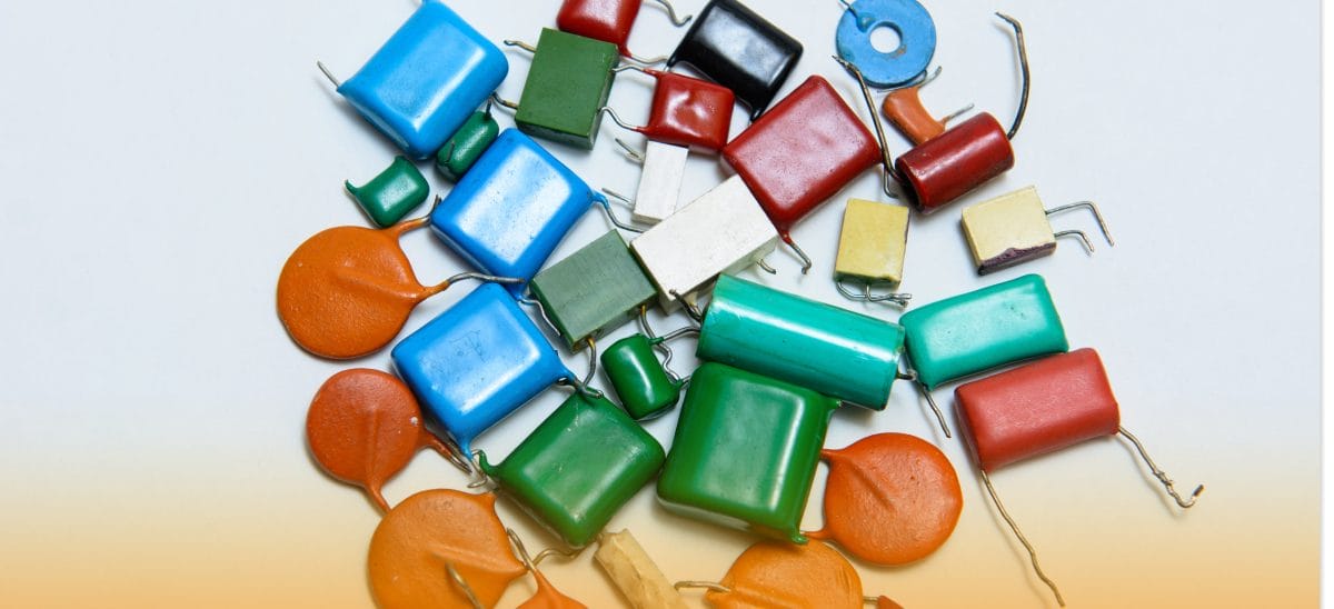
(Capacitors made of metals, ceramics, and films)
The Capacitance Conversion Table
As we mentioned earlier, capacitance units are in terms of microfarads. However, it is relatively common to find other manufacturers showing the MFD capacitor ratings in nanofarads (nF) and picofarads (pF). Consequently, you will find that a 0.1uF capacitor has a rating of 100nF.
It could also have large values in picofarads representing the same thing. In such a case, you might have your capacitor specifications in uF, but the available capacitors are in either pF or nF. The conversion table below should help you determine the capacitance in the units you’d prefer.
| uF (Microfarad) | nF (Nanofarad) | pF (Picofarad) |
| 0.001 | 1.0 | 1000 |
| 0.0015 | 1.5 | 1500 |
| 0.002 | 2.0 | 2000 |
| 0.0025 | 2.5 | 2500 |
| 0.003 | 3.0 | 3000 |
| 0.0035 | 3.5 | 3500 |
| 0.004 | 4.0 | 4500 |
The Conversion Formula
Converting between uF, nF, and pF is done through manipulation of factors as shown below:
| Converting | Multiplication Factor |
| uF to nF | 1.0 x 10³ |
| uF to pF | 1.0 x 10⁶ |
| nF to uF | 1.0 x 10⁻³ |
| nF to pF | 1.0 x 10³ |
| pF to uF | 1.0 x 10⁻⁶ |
| pF to nF | 1.0 x 10⁻³ |
Using a Digital Multimeter to Measure Capacitance
The electrical charge stored in an MFD capacitor is through parallel conducting plates with a dielectric between them. The capacitance refers to the amount of charge that a capacitor can handle. A digital multimeter is a measurement instrument designed to determine different electrical parameters, including capacitance.
To measure the capacitance, you will have to switch to MFD on the DMM. Additionally, testing means that you have first to discharge the capacitor since it might still have some electrical energy stored in it.
Discharging requires connecting a resistor or a thick copper wire between the two terminals of the capacitor and waiting for a while. It happens to make sure that all the energy dissipates for your safety. Follow the steps below when measuring capacitance using a DMM:
1-Provide insulation by covering the thick copper wire with tape: this way, the current won’t flow or cause harm.
2-Disconnect the power source to the MFD capacitor
3-Take the insulated copper wire and connect the capacitor terminals through the bare end. Wait for about 30 seconds for the capacitor to discharge. If you notice that the wire gradually gets hot, disconnect it, and give it some time until it’s cool. Perform the discharge process for another 30 seconds until you are sure that the capacitor has no charge left.
4-Take the multimeter and set it to MFD for capacitance. Press the DMM probes against the capacitor terminals to get a reading
5-Take the multimeter reading shown on the DMM screen and compare it to the value printed on your MFD capacitor.
The MFD Calculation Formula
You can use the formula below to determine the MFD rating of your capacitor accurately:
(159,300 + Hz) x (volts + amps) = MFD
This formula simplifies to just one number if the Hz parameter doesn’t change.

(A digital multimeter)
Choosing the Right MFD Capacitor Size
Choosing the right size of a capacitor depends mostly on where you intend to use it. Likewise, you must obtain the right size of MFD capacitor, especially if you’re using it to run a motor. Motors are familiar with refrigeration units and air conditioning systems. The capacitor is what will ultimately determine whether or not a motor starts.
Among the key factors determining the capacitor’s size are the voltage and starting prerequisites of a motor. Above all, if you want more starting torque on your motor, it will help adjust your MFD capacitor rating.
The best way to do that would be to replace the capacitor with one of a higher rating. However, there are factors that you need to consider to make sure that there is reasonable power efficiency. You will also need to factor in temperature, rated motor speed, and power limits.
With capacitors, there is always some wiggle room when it comes to setting the right MFD rating. A tolerance level of ±6% is ideal for a capacitor-run motor. It means that a 50 MFD capacitor can be between 47.6uF and 52.4uF and still serve its purpose. Therefore, anything below that rating isn’t ideal for functionality.

(A capacitor inside a pump motor)
Improving Power Factor Using KVAR Formula
An MFD capacitor can also serve to improve the power factor for better power efficiency. It can accomplish this because the current through will always lead to the supply voltage. Additionally, you can obtain the MFD capacitor rating required for this exercise through the formula below:
Capacitance = KVAR / {2 π f V2}
Summary
It is quite clear now that MFD capacitors are essential in the fabrication of electronic products. In particular, these components play a vital role in the functioning of PCBs. Having a good understanding of them helps you use these essential components properly.
Here at WellPCB, we pride ourselves on acquiring knowledge and understanding the different challenges of electronic products. Feel free to contact us anytime as we continue to tackle and solve even more electronic issues. We will discuss more knowledge together to help you produce better-quality electronic products.