Contents
What is a Micro Ampere Meter?

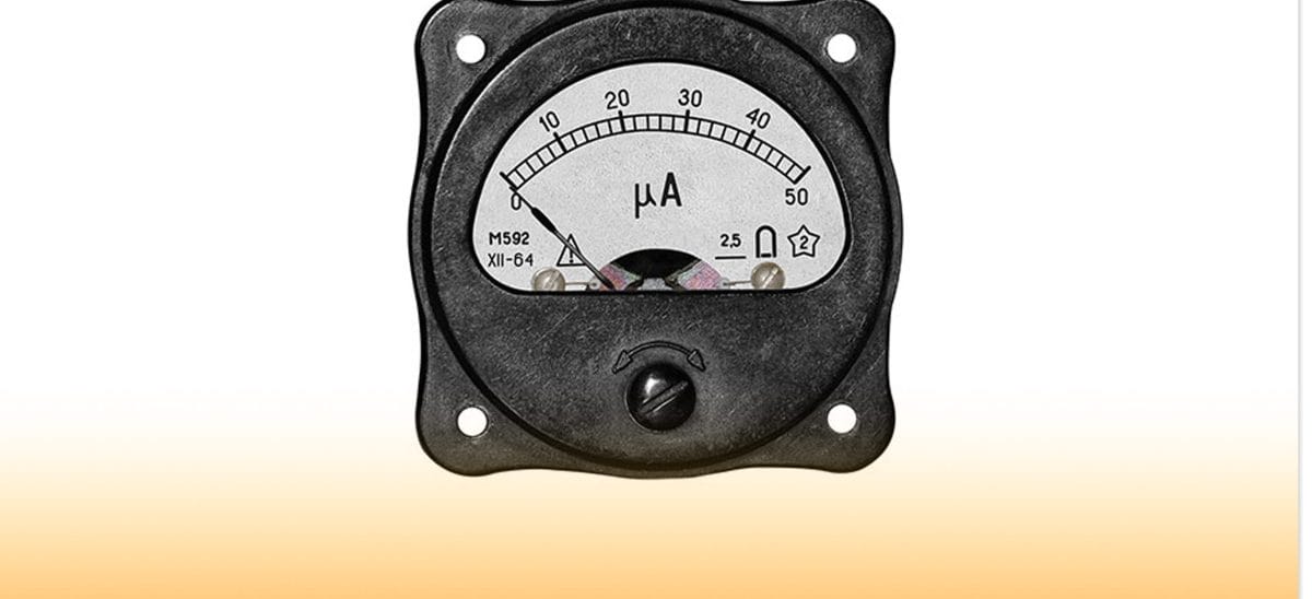
Figure 1: A Black Microammeter
The microammeter/ microamp meter is an electronic component that is essential in measuring current in the microampere range. Most conventional electrical instruments for measuring current operate in the milliampere range or larger currents.
Among the key advantages of the microampere meter include the following:
- First, it can be useful as a standalone device like the conventional multimeter or as part of a larger device/component that needs a sensitive current meter.
- Also, it can be useful in both low-current and high-current measurement scenarios.
- Thirdly, the device has a relatively low voltage resistance; its standard input resistance is also significantly low.
- Among its vital product details is that it features a cover with efficient impact resistance. Hence, it’s a more durable device than some of the typical electricity meter scales.
Features

Figure 2: A Round Microammeter
Among the key features of the current meter include the following:
- It measures DC electric current in the range of 0 ~ 200uA, and its operating voltage is +5 V +/- 5%.
- Also, it has an operating humidity of 10 ~ 80% in non-condensing conditions.
- Besides, the device has an operating temperature of between -10 to +50°c and a Working pressure of between 80 to 106kPa.
- Lastly, its measurement rate is greater than or equal to 2 times / S and has a 4-digit LED display.
How does the Circuit work?
First, you must interact with the active circuit below to understand how the micro amp meter makes accurate measurements.

Figure 3: Circuit Diagram
Primarily, the device features six-ampere ranges, i.e., between 100 nA to 10 mA. The high levels are handy in ensuring the device can detect even the most minor current changes.
Also, from the circuit, you’ll note that resistors R10 and R11 are handy in creating a 1V FSD voltmeter in conjunction with the meter. In addition, the circuit features an operational amplifier 1C1, which gives up to 100 times Direct Current voltage gain. In this specific circuit, the amp is set in a non-inverting configuration.
Also, we have capacitor C1, which regulates the AC gain and cushions the circuit from stray interference pick-up. It also improves the circuit’s stability.
Besides, the circuit needs a high input impedance to ensure limited input current loss. Thus, we use a FET input operational amplifier with a 15M megaohms standard input resistance.
Finally, the circuit has diodes D1 and D2, which shield it from a current overload. They limit IC1’s output voltage to within 1.3 volts.
How do we use the Micro Ampere Meter?

Figure 4: A Microammeter
The following procedure outlines how you can use the amperemeter to measure the current flow rate:
- Primarily, you need to disconnect the circuit and connect the microampere meter in series. In this case, you may use either an AC voltage current display meter or a DC one.
- Also, when making the connections, ensure you connect the positive ends of the meter to the designated positive terminal of the device you’re measuring.
- Next, run the current and check the meter needle deflection for the current reading.
- Note that your ammeter should be in series with the current flow. Otherwise, a parallel connection will have current passing only through the meter, thus giving you an incorrect measurement.
Conclusion
From this post, you now know the working principle of a microampere meter. Due to its accuracy, you’ll find the component in most current sensitive devices such as thermocouples. For further questions, talk to us, and we’ll respond immediately.


