
Contents
PIR (Passive InfraRed) Human Movement Detector Circuit using Operational Amplifier
Our first practical application of a motion sensor in a circuit requires an op-amp.
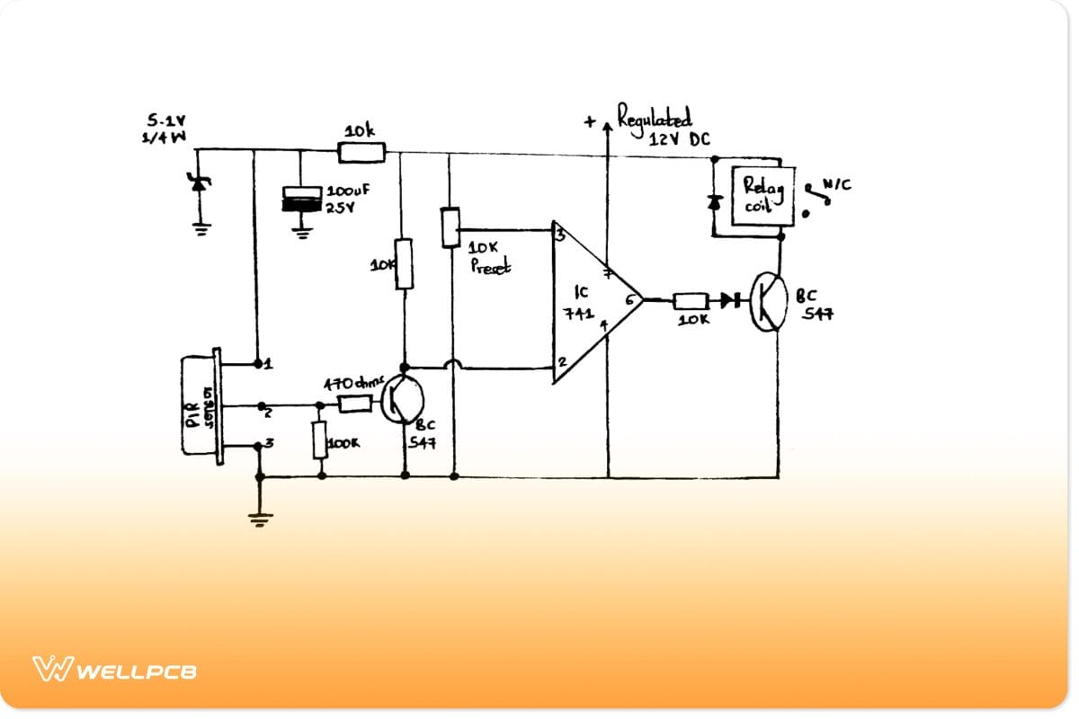
Motion detection circuit diagram using Op-amp
Circuit explanation
- When there’s human IR radiation, the sensor will sense the radiation before immediately converting it into minute electrical pulses. Consequently, the collector goes low since the pulses trigger the transistor to start conducting.
- Then, we have IC 741 as the comparator, with pin2 as the sensing input and pin3 as the reference input. If the transistor’s collector goes low, pin2 potentiality decreases than pin3 potentiality. As a result, the IC’s output increases and triggers the relay driver stage comprising a different relay and BC547 transistor.
- Afterward, the relay will activate and turn on your connected alarm device.
- Lastly, the capacitor 100uF/25V ensures the relay is constantly on after the PIR deactivation due to the radiation source exiting.
Note; Our PIR device above is difficult to optimize and very sensitive. So, you can enclose the sensor inside a Fresnel lens cover to stabilize its sensitivity and improve the detection radial range. Alternatively, use a readymade PIR module with enhancements.
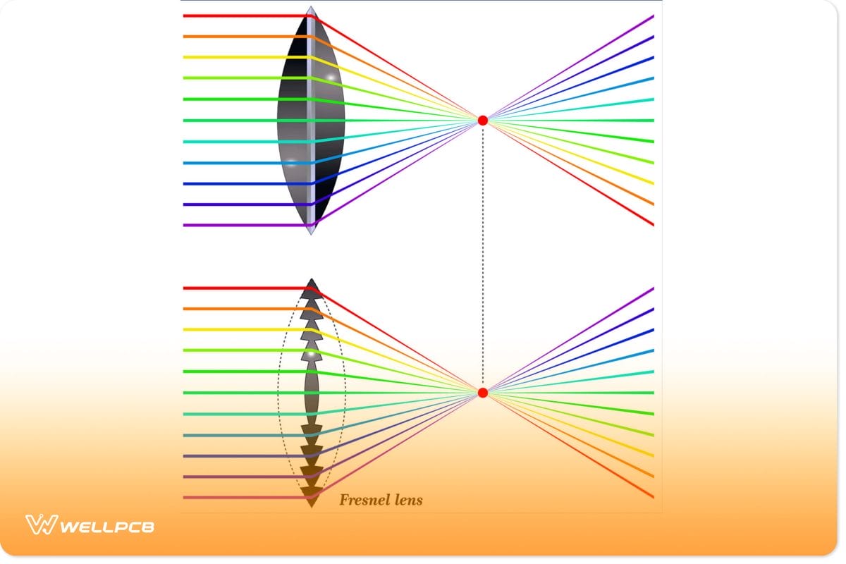
(light collimation with Fresnel lens)
PIR Motion Detector and Security Alarm Circuit
Secondly, we have our second circuit that you can use as an anti-theft alarm circuit.
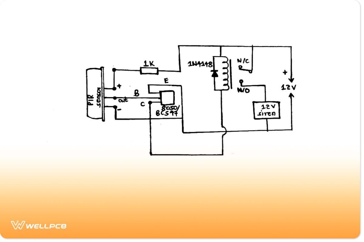
Security alarm circuit
From the diagram, you’ll only need a relay to configure externally, a transistor, and a single 1K resistor. Besides building it yourself, you can also buy a readymade version of the sensor.
As for its 12V power supply, a 12V 1amp SMP circuit should be enough.
- Motion Sensor Light Switch Circuit Diagram
The motion sensor light switch circuit works at night and during the day. Thus, it is ideal for security light and alarm use.
Components needed

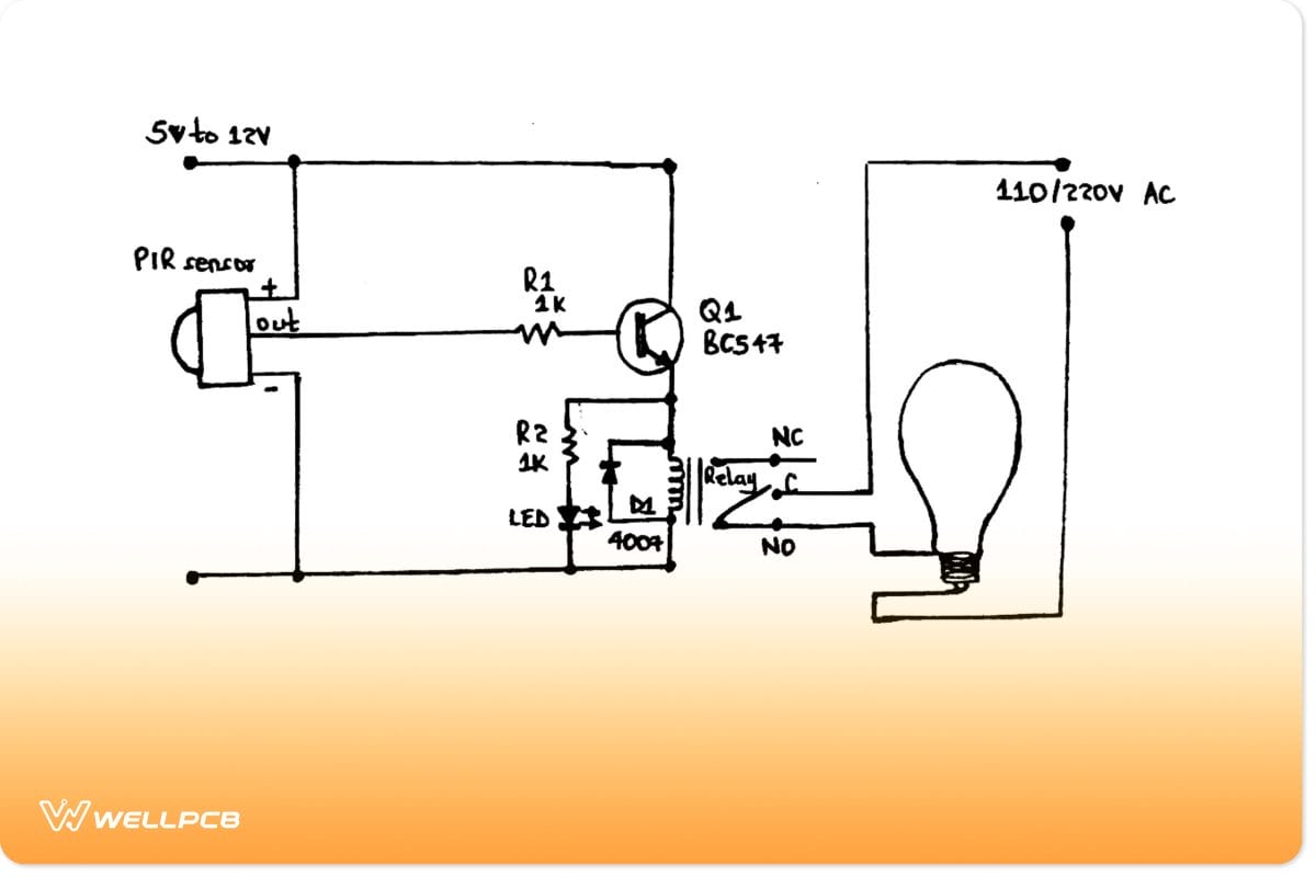
Motion sensor light switch circuit
Circuit explanation
- Since the required voltage ranges from 5V to 12V DC, you can use a 5V voltage regulator LM7805.
- Now, connect the sensor’s output with the base of the NPN transistor, the ground pin with negative DC supply, and the sensor’s VCC pin with 5V DC.
- Next, apply a relay according to the input voltage to be able to connect any light.
- The sensor will have a low output with the transistor switched off if no motion occurs, causing no input transmission to the base terminal. However, when it detects motion, the work becomes high. Subsequently, the transistor receives a high input at its base terminal and switches on before activating the relay. Then, the LED you’ve connected to the relay will produce light.
- It’s good to note that the sensor’s output is usually low after the duration of time you’ve set. Hence, the light or alarm connected to the really will automatically remain switched off a while later.
Note; When only using an alarm, connect it directly with the power supply and transistor’s collector without using a relay. Additionally, you’ll not need the regulator, just a direct 5V power supply.
- The PIR sensor here consists of two presets;
- An adjustment of time delay with constant high output for some time and
- An adjustment of sensitivity
An Industrial Motion Sensor Circuits
Some components to use here include an IC, LDR, and other passive components. The circuit works by detecting the motion of a cylinder that illuminates the specific LEDs for the needed detection.
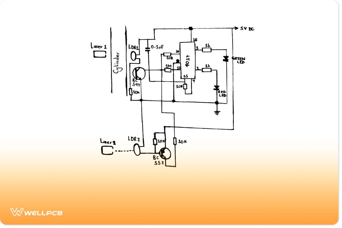
An industrial motion sensor circuit
Circuit explanation
- When you switch on the power, you reset the IC via the 0.1uF, enabling the green LED to illuminate first. At the same time, sensor-B (LDR2) and sensor-A (LDR1) get lights focused on them by relevant laser beams.
- LDR2 switches on the BC557 transistor, whereas LDR1 switches on the BC547 transistor and keeps them triggered. And so, the IC’s pin14 receives supply voltage from BC557. But, remember BC547 and LDR1 are also conducting. Therefore, the circuit grounds the potential, leading to a net potential of zero or logic low at pin14.
- Then, while the cylinder is lowering and coming in front of LDR1, it elevates LDR1 resistance by blocking the beam and then shuts off BC547. Afterward, BC557 voltage hits pin14 and produces a forward sequence at the IC output. It then causes the red LED to illuminate and shuts off the green LED.
- The cylinder moves further downwards and blocks beams from reaching LDR2. So, the LDR2’s resistance lowers and stops the transistor’s conduction, causing the potential to be zero at pin14. IC only responds to positive pulses and, hence, isn’t affected.
- As the cylinder moves upwards in reversion, it unblocks LDR2, allowing it to receive the beam. Then, BC557 begins to conduct by releasing a positive pulse that hits pin 14 of the IC. Later on, the red LED shuts off while the green LED illuminates.
Build Simple Motion Detector Circuits using 555
Lastly, we have a simple motion detector circuit using a 555 timer.
Components needed
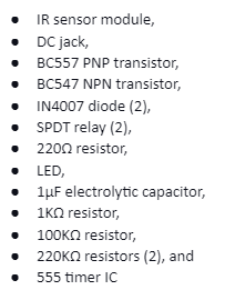
A simple circuit motion detector using a 555 timer
Circuit explanation
- First, connect pins four and eight and pins six and two.
- Then, connect the voltage divider circuit’s output to pin six of the Integrated circuit.
- Next, use a 1uF capacitor to connect one of the voltage divider circuit’s resistors to output pin three via a resistor (100K).
- Apply a relay in the driver circuit between the positive terminal of the capacitor and pin two.
- Also, connect the LED to the IC output via a current limiting resistor.
- The NPN transistor controls the output relay. Therefore, use a 1K resistor to connect it to the IC’s output pin three.
- Finally, connect the PNP transistor base that drives the switching relay to the IR sensor module output.
Motion Sensor Applications
You can find motion sensors in the following applications;
- Automatic doors,
- Hand dryers,
- Automated sinks/toilet flusher,
- Security lighting,

(home security light)
- Entryway lighting,
- Automatic ticket gates and
- Intruder alarms in homes, banks, shopping malls, and offices.
(house alarm)
Conclusion
Briefly, a motion detection circuit senses the direction of motion of an object and gathers data regarding its velocity, acceleration, and position. The sensors are easy to build, and you can contact us for any inquiries.


