Contents
How a Motionless Electromagnetic Generator Works
The interaction of three components, ferromagnetic core, coils, and permanent magnets, and their placement contributes to a MEG’s operation.
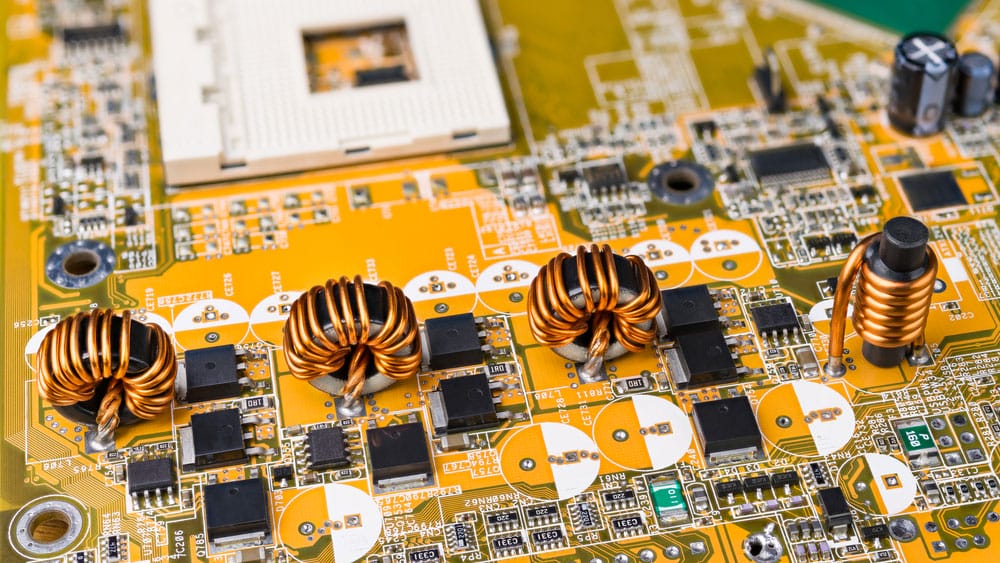
(four inductors with ferromagnetic core on circuit board)
It generally has the potential to produce a voltage output signal greater than the triggering power of an induced input.
MEG devices Often Have Several Winding Sections Whereby;
- The first output coil and input coil (induction coil) function on the regions of the 1st magnetic path.
- Then, the second output coil and input coil work along with the areas of the 2nd magnetic path.
During MEG functioning, you’ll alternately agitate the input coils over an external pulsating Direct Current. A similar pulsating current across the secondary coils gets induced by back EMF from input coils. You can often achieve that at a specified rate and magnitude.
On measuring the magnitude of input power by inventors, there’s an improvement in COP3.
Note;
COP stands for coefficient of performance. Therefore, COP3 signifies a 3-times increase in output power than the input power. In other words, when you have like 1W of input power, the output power will generate 3 watts of power.
In actuality, the MEG device doesn’t disrupt any law of thermodynamics. Hence, the COP value increase is because the central ferromagnetic core interacts with the application of a permanent magnet and coils.
Our projected MEG circuit uses the principle of rallying the dormant power stored in the permanent magnet. Then, the power generates an electrical energy output greater than the triggering pulses of applied input.
Basic Coil and Magnet Layout Set up for a motionless electromagnetic generator
The two diagrams above give a simple setup or layout of the core, magnets, and coils. One image shows the top view of MEG, while the other shows its side view.
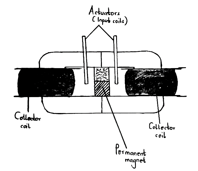
Side view of MEG device

Front view of MEG device
- The unshaded part represents the collector coils you wound over some plastic bobbins. When there’s a concentrated or accumulated pulsating electromagnetic field, the coils react with it. Afterward, the coils convert the magnetic field into COP3 over-unity output or COP3 electrical energy.
- Additionally, the shaded part stands for a magnetic core in a 2 C-cores structure with an edge-edge attachment. The laminated iron C-cores should also have a frequency ranging from 50 to 200Hz. Thus, it will require experimentation to determine the optimal outcome as per the COP value.
- Also, there are smaller trigger coils (actuator/ input coils). The external power supply source produces pulsing DC input that the coils receive. Further, you’ll need to alternately pulsate the coils at a frequency specified by the core specification.
- Finally, some magnets are neodymium types.
(preparing neodymium magnet)
Motionless Electromagnetic Generator Circuit Diagram
The circuit diagram below shows how you can effectively power up the primary coils in a MEG device.
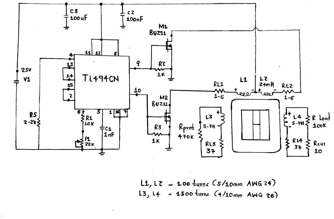
A motionless electromagnetic circuit diagram
Conclusion
In summary, producing electrical energy from electric currents or an electric field can be easily achieved through electric generators. One way is by using a motionless electromagnetic generator, as discussed in this article.
We hope you won’t hesitate to reach out to us for clarification.