Good music, as they say, is food for the soul. Operational amplifiers form an integral part of audio systems, and damage to it affects the audio output. Therefore, if your sound system produces noise feedback, there are a couple of possible solutions. One of them is to use a NE5532 preamp circuit.
But why the NE5532 preamp IC? For its high-quality sound and efficiency, of course. Ideally, the preamplifier IC works by increasing the input signal. As a result, your audio equipment sounds a lot better, in general. So, don’t just consider a more prominent speaker or amplifier. Instead, consider setting up an op-amp tone control circuit for yourself.
Contents
The Composition of NE5532 Preamp
Technically, the NE5532 Preamp IC is a device capable of converting electrical pulses into sound signals. In other words, they make up the basis of an audio amplifier. Some notable characteristics include low distortion, high power output, and efficiency.
So, by composition, the NE5532 preamp comprises of three major parts:
- The tone control device
- Power amplifier circuit
- Preamplifier circuit.
NE5532 Preamp Circuit Working Principle
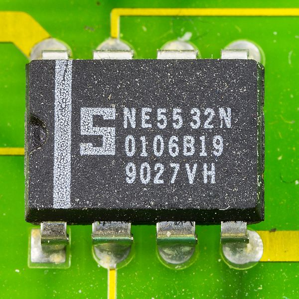
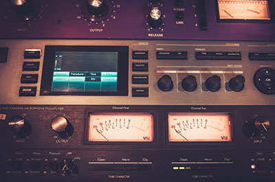
(A dual noiseless NE5532N op-amp on a printed circuit board)
Source: Wikimedia Commons
Conventionally, the working principle of the NE5532 preamp IC follows basic processes. More so, in terms of the circuit input signal, whereby the C1 and R1 carry them. Afterward, they send and filter the call to the input of IC1 (PIN 3).
On rotating S1, you choose an input channel. So, for any choice you make, each of these channels differs in amplitude. For instance, selecting a track to a position on the microphone signal gives you an amplitude of 50mV.
Then, AV multiplied by the input amplitude gives us a value – of the output operating voltage. Therefore, any change in input position always results in 1 Vrms of the output amplitude.

NE5532 Pinout Configuration
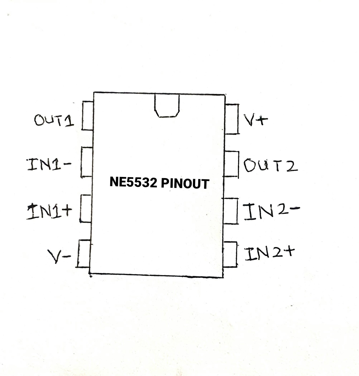
(NE5532 PINOUT IMAGE)
Source: Wikipedia
This multipurpose audio amplifier transmits signals via the eight input pins on the IC. The list is as follows:
| PIN | PIN name | Description |
| 1 | Out 1 | It is the output for the inverting signal input pins 2 and 3. |
| 2 | IN 1 (-) | On the left side of the IC is the first amplifier input pin with a negative terminal. |
| 3 | IN 1 (+) | IN1+ is the second input pin with a positive terminal. |
| 4 | VCC- | The ground terminal or negative voltage supply. |
| 5 | IN 2 (+) | On the other side is the second input pin with a positive terminal. |
| 6 | IN 2 (-) | Also, in this same area is the second input pin with a negative terminal. |
| 7 | OUT 2 | It is the second output for the inverting signal input pins 5 and 6. |
| 8 | VCC | The last pin is the positive voltage supply. |
How to Build a NE5532 Preamp Circuit
Below, we take you through four different circuits. Additionally, we explain all the processes and parts you need when building a NE5532 amplifier IC.
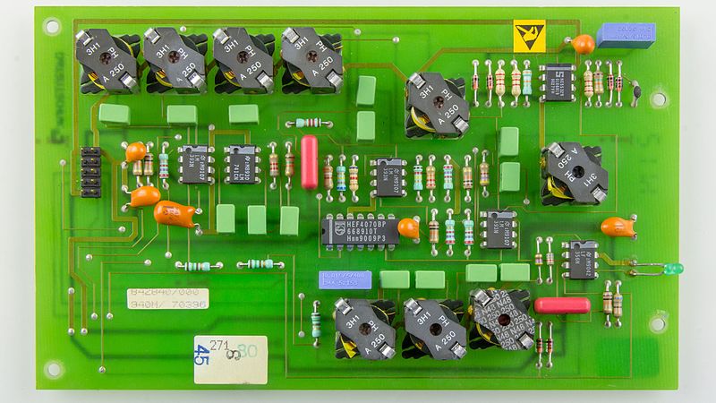
(An operational amplifier integrated circuit on a printed circuit board).
Source: Wikimedia Commons
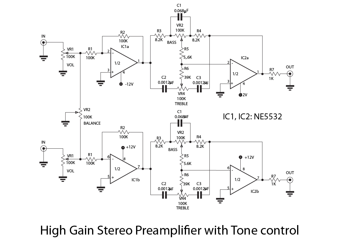
Circuit #1: Pre-tone Control Stereo Amplifier using NE5532
For the best pre-tone control stereo amplifier, you are better off with a high-quality op-amp package.
How to build/use the circuit
The circuit comprises dual parts. We have the preamplifier part on one side, and on the other is the circuitry with a passive Baxandall tone control.
You express your voltage gain in a non-inverting input mode. Then, R2 functions as your feedback resistor, and the second resistor works in conjunction with the R1 to produce completed output.
For project accuracy, use the equation: Av = (R2/R1) + 1.
Moving on, the video link below shows you a practical application on how to use this circuit.

(Circuit diagram showing the connections of a simple Baxandall pre-tone control stereo built with an op-amp)
Source: Wikimedia Commons
Circuit #2: Bass-Medium-Treble Control Circuit
In practice, the first circuit is not entirely suitable for all projects, and it is because it cannot handle total sound range adjustment. Although both courses have similar building parts and processes, they have their differences.
Parts Needed
Below, we list the required parts for an audio preamp circuit with treble, medium, and bass signal control.
| Part Name | Rating | Quantity |
| NE5532 IC | — | 1 |
| Capacitor | 104 pf | 2 |
| Capacitor | 103 pf | 4 |
| Capacitor | 222 pf | 2 |
| Resistor | 15k | 2 |
| Resistor | 1k | 4 |
| Resistor | 10k | 6 |
| Resistor | 160k | 2 |
| Resistor | 47k | 2 |
| Resistor | 2.7k | 2 |
| Resistor | 100 Ohms | 1 |
| Capacitors | 10uF/25V | 4 |
| Capacitors | 47uF/25V | 4 |
| Capacitors | 1000uF/25V | 1 |
| Variable Ohm Resistors | 2k | 2 |
| Potentiometers | 47k | 6 |
| Zener Diode (IN4742A) | 12V | 1 |
How to build/use the circuit
Below is a circuit diagram for a concise and practical illustration of the building process.
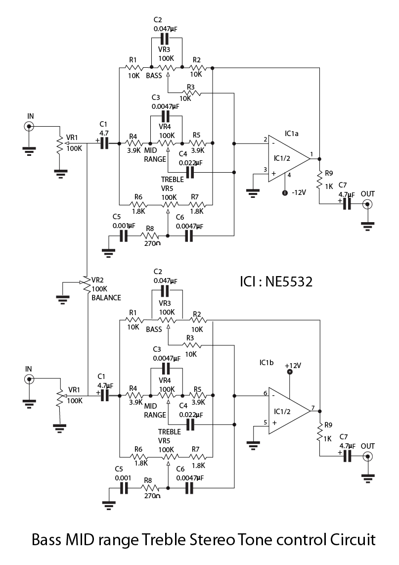
(A Bass-MID-Treble tone control circuit showing the NE5532 IC connections)
Source: Wikipedia.
Circuit #3: Super Preamplifier tone control circuit project using NE5532 and LF353
First, let’s get an idea of what tone controls are. Usually, they are of two types: passive and active tone control. The dynamic tone control has a better input signal, and therefore, it is our preferred choice for this circuit.
Parts Needed
| Part Name | Rating | Quantity |
| NPN Transistors, Q1 & Q2: BC549 | 45V, 100mA | 1 |
| IC1: NE5532N or LF353, Wide Bandwidth Dual JFET Input Op-amp | — | 1 |
| 0.25W +/- 1% Ohm Resistors:R15 | 3.3K | 1 |
| R14, R13, R10 & R7 | 100K | 1 |
| R6 | 2.2K | 1 |
| R12, R11, R9, R8 & R4 | 10K | 1 |
| R3 | 270K | 1 |
| R2 & R16 | 100 Ohms | 1 |
| R1, R5 & R15 | 2.2K | 1 |
| Electrolytic Capacitors: VR3 CT (non-Linear Pot.) | 50KA | 1 |
| VR1 & VR2: (Linear Pot.) | 100KB | 1 |
| C1, C2, C7 | 10uF 16V | 1 |
| C12, C13 | 100uF 25V | 1 |
| Polyester Capacitors: C10 & C11 | 0.1uF 50V | 1 |
| C9 | 0.01uF 50V | 1 |
| C8 | 0.001uF 50V | 1 |
| C5 & C6 | 0.047uF 50V | 1 |
| C3 & C4 | 0.0047uF 50V | 1 |
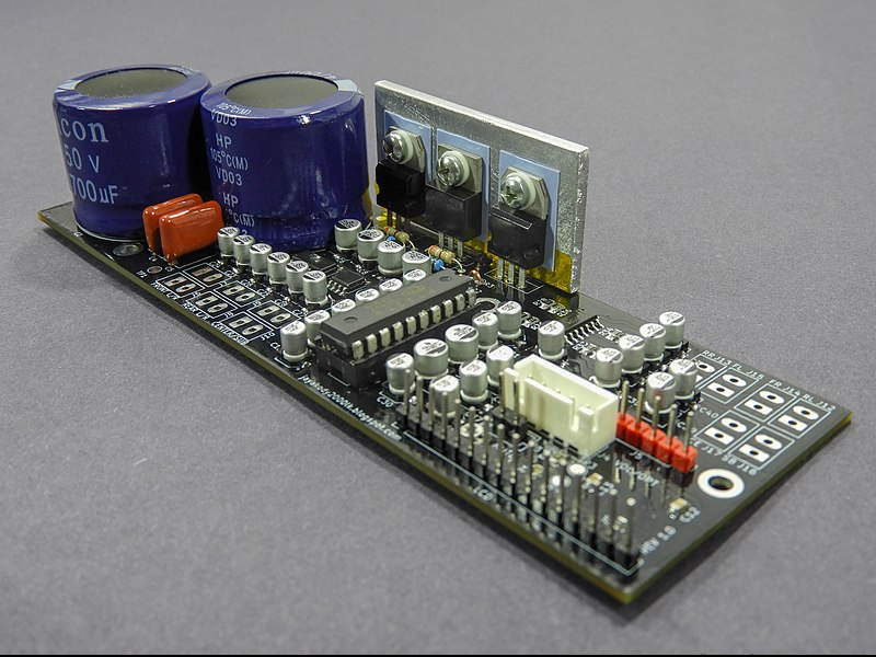
(A picture of preamplifier tone control IC)
Source: Wikimedia Commons
How to build/use the circuit
(A super stereo preamp tone control circuit showing the NE5532 IC connections)
Source: Wikipedia
- First, you are to assemble these components on a PCB. But before anything else, we need to understand the working principle to understand the circuit’s operation. For this reason, we need to get the basic feedback circuit of the op-amp. So, to begin, you need to use the formula Rb/Ra to calculate circuit figures.
- Next, connect R1, C1 with R2 + C2 so that the impedance value decreases with an increase in frequency. On adjusting VR1, the value of Ra1 exceeds C1 + R1. Thus, there’s an increase in one line of the circuit.
- Adjusting the volume in the reverse direction increases gain on the opposite line. VR1 works as your treble control.
- Furthermore, readjusting the values of C4 + R4 and C3 + P3 gives you a higher resistance. As a result, this lowers the frequency as well as the circuit gain.
- Now, you need to adjust the treble and bass signal separately. The end product to aim for is a sequential 2-stage tone control circuit. Therefore, you must prevent any interference between both controls.
- So, the transistors Q1 & Q2 function as the matching circuit. Also, the LF353 (IC1) serves as an adjustable treble sound. The NE5532N, on the other hand, (IC2) works as the bass.
Summary
In conclusion, these circuits are all unique, in one way or the other. We still see some standard features now and then, such as the negative and positive ground.
At this point, you have learned a few practical things about preamp circuits. So, are you considering using a NE5532 preamp for your next audio circuit project? Perhaps, you are not sure exactly how to begin. Visit our contact page to talk to our experts.


