
You may notice that the sound from your music player or listening device seems distorted or unclear. That’s usually due to a poor amplification process that allows unwanted high or low electronic noise frequencies to pass through. Now, a simple solution to this problem involves integrating a specialized noise filter circuit. These generally consist of an op-amp, capacitors, resistors, etc. you will typically find on an ordinary circuit. Placing these basic components in a specific setting will improve the overall sound because they amplify the signal. We wrote this article to provide you with more knowledge on this particular subject. So let’s take a look!
Contents
1. What is a Noise Filter Circuit?
Noise filter circuits generally allow specific frequencies to pass through. At the same time, they also remove undesirable frequencies from a noise signal that otherwise interfere with operation. Overall, these simple, inexpensive components help reduce signal line noise interference on a circuit. Additionally, these block common mode noise for electrical systems, vehicles, and industrial equipment.

(A noise circuit will help improve the sound quality of a listening device.)
Furthermore, these reduce white noise, the most common source of electrical noise. This occurs due to electrons colliding with each other. Also, noise power corresponds to absolute temperature, also referred to as thermal noise. Cameras for astronomy circuitry undergo a cooling down process due to that thermal dependence.
2. Principles of Noise Filters
Noise filters serve as a circuit element that contains inductors and capacitors. Inductors present low impedance properties relevant to a low-frequency electronic component. They also feature high impedance for components exhibiting high frequencies. Thus, this means that signal frequencies will not pass through if the impedance increases.
Placing an inductor in series on a circuit’s noise path will cause it to block out high-frequency signals. At the same time, it allows low frequencies to pass through.
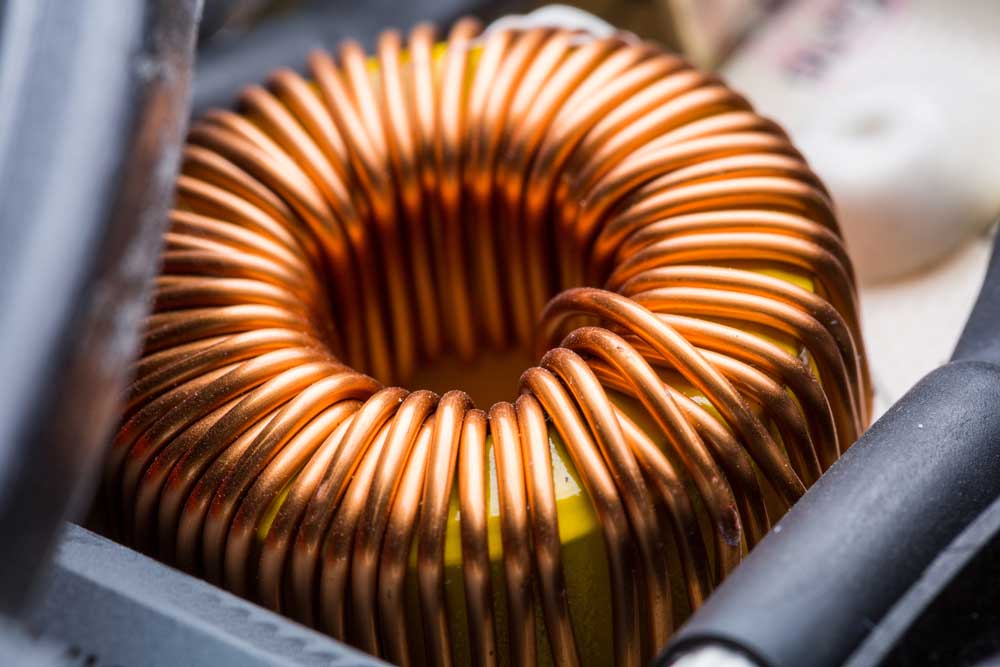
(An inductor can help reduce noise on a circuit.)
Meanwhile, capacitors present a high impedance for low-frequency components. Additionally, they exhibit low impedance for components with high frequencies.
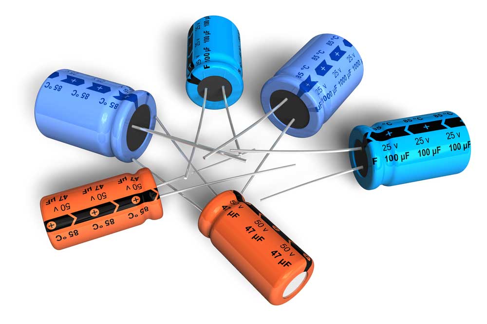
Capacitors typically integrate between the GND and noise path. In effect, these can transmit the high-frequency noise either to the ground connection or power supply. At the same time, low frequencies pass through. Therefore, this results in the capacitor bypassing noise current.
(Capacitors integrate between the ground line and noise path.)

3. Main Types of Filters
(Different filter types provide various characteristics.)
Four main types currently exist, the low-pass filter, high-pass filter, band-pass filter, and notch/band-reject filter. However, the low and high represent the cutoff frequency levels rather than absolute frequency values.
- Low-pass – Low-pass filters prevent high-frequency signals from passing through. Meanwhile, low frequencies can pass through a circuit.
- High-pass – The high-pass filter blocks low-frequency signals while allowing high frequencies to pass through.
- Band-pass – A bandpass filter allows frequencies in a certain range to pass through while blocking out the rest.
- Notch/band-reject – A notch filter, also called band-reject, blocks a certain frequency band while other frequencies pass through.
4. Noise Filter Circuits Projects
You can integrate a noise filter for many applications. We described a few concepts that you can implement below:
Clipping Amplifier circuit using BC109
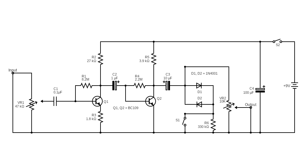
(The clipping amplifier circuit diagram.)
If you raise the volume to the highest setting while listening to music, you will notice that the sound seems distorted. That’s because the sound signal did not fully amplify. As a result, the sine waveform generates a low signal due to the affected waveform, resulting in poor sound quality.The clipping amplifier circuit generally boosts poor audio signals to improve the sound. It relies on capacitors, resistors, switches, a battery, and two BC109 transistors to perform this amplification process. The components work together to boost the signal’s waveform. Therefore, the sine waveform’s peak provides similar qualities as a sine wave.
Audio enhancement for an analog amplifier
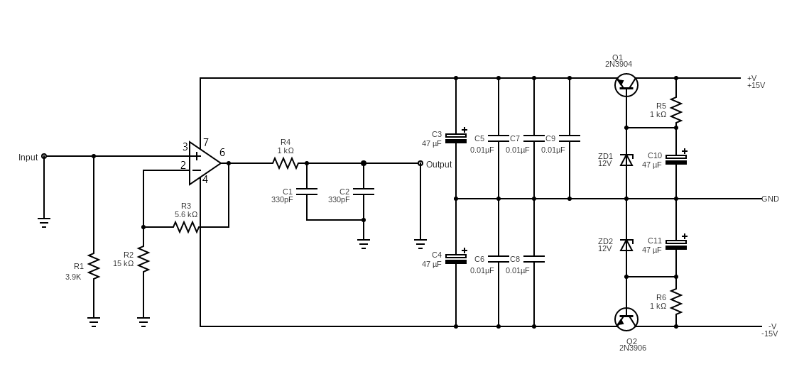
(Audio enhancement for an analog amplifier circuit diagram)
CD players can sometimes provide poor audio quality, hindering a user’s listening experience. That’s because the IC op-amp exhibits a slow slew rate. Generally, this means it’s incapable of matching the digital signal’s modification due to the shortened frequency response. In effect, this produces poor sound with sharp and hard qualities.
A highly efficient analog output amplifier with an integrated filter that removes undesired noise will help solve this issue. For this reason, we chose to utilize a high-quality LEWIS Garret op-amp. The circuit contains an IC (Q1, Q2, ZD1, ZD2, R5, R6, C10, and C11) that isolates the voltage when the power increases. Meanwhile, the C5-C9 bypass capacitors serve as a collector. These respond to high frequencies while reducing the voltage leakage sourced from capacitors C3 and C4.
The input will transmit a signal to the op-amp’s pin 3 terminal. From there, pin 6 distributes that signal to the R3 and R2 resistors, preventing it from phasing out. Afterward, C1 and C2 capacitors operate together to filter out undesirable frequencies.
Overall, this circuit boosts the audio signal of a CD player. The circuit’s high input prevents the CD player’s original amplifier from loading. It also features low output resistance, allowing a simpler process for driving loads.
Simple audio noise filter
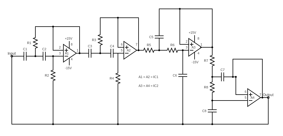
(Schematic diagram of a simple audio noise filter)
The simple audio noise filter circuit, as shown above, prevents unnecessary signals from passing through. These signals usually mismatch the audio frequency level, which means they exhibit higher or lower values.
This circuit contains both a high pass filter and a low pass filter that operates at 24 dB octave. Plus, it exhibits a 3 dB cutoff frequency at 10.7 kHz and 11.3 Hz. Modifying the capacitors’ and resistors’ values will result in a change of bandpass properties. You can also increase the bottom cutoff frequency by lowering C1 to C4’s values. However, increasing those values will result in a lower bottom cutoff frequency.
Then, applying higher values on R5 to R8 will lower the top cut-off frequency. If you want to raise the top cutoff frequency, you must lower those values.
Conclusion:
Overall, a noise filter circuit provides sound amplification capabilities. In that context, it will allow crucial frequencies to pass through while blocking out unwanted frequencies. This process reduces electrical noise, making the output signal much cleaner. As a result, you will notice a significant improvement in your audio device’s sound quality. So now you can enjoy listening to music without worrying about missing a beat!
Do you have any questions regarding a noise filter circuit? Feel free to contact us!


