
Contents
What is Overvoltage Protection?
Overvoltage protection is a power supply feature that clamps the output or shuts down the power supply at higher voltage levels. Often, the voltage level must exceed the preset level for the protection to occur.
An over-voltage protection circuit mainly prevents damage to the electronic elements of many power supply devices. Because of that, overvoltage protection is currently quite popular in several applications, such as automotive applications.

(cars)
Overvoltage Protection Type
Types of overvoltage protection depend on cost, performance, and complexity. They all achieve an efficient power supply over-voltage protection.
The most common three are;
SCR (Silicon Controlled Rectifier) crowbar
An SCR crowbar circuit prevents an overvoltage by creating a short circuit crossway to the output of a power supply.
SCR thyristors can switch large currents and be active till any charge disperses. Also, you can link back the SCR to a fuse that’ll blow and keep the regulator from receiving more voltage.
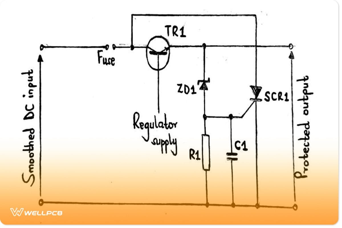
SCR crowbar circuit
In the circuit, the Zener diode functions to keep a higher voltage than the operating voltage of the output. Similarly, it maintains a low voltage level to prevent circuit damage.
Therefore, the Zener diode has no current flow during conduction because it doesn’t get a breakdown voltage. Consequently, it currently doesn’t flow through the thyristor, keeping it shut. However, the power supply operates as usual.
(Zener diodes)
The voltage often rises when the series pass transistor in the DC power supply fails. The unit decoupling, fortunately, keeps the voltage from instantly growing. The voltage rising gets to appoint where the Zener diode starts conducting. Subsequently, current flows through the thyristor gate and causes it to trigger.
After the triggering, the thyristor shorts the power supply output to the ground, thus avoiding damage to its circuitry. You can also use the short circuit to blow a fuse, thereby diverting the power from the voltage regulator. The diversion prevents the unit from having further damage.
(thyristors)
At times, you can place a small capacitor as a decoupling unit from the thyristor gate to the ground. The purpose is to prevent RF or sharp transients from the decoupling team receiving power. In that way, the RF won’t get to the gate connection and cause a false trigger.
Keep off a huge decoupling since it can slow down your overvoltage protection even in a realistic case of failure.
Voltage clamping
Voltage clamping is our second form of over-voltage protection.
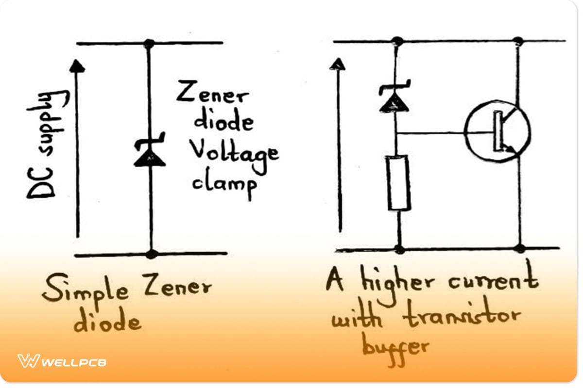
The Voltage clamping circuit
Its operation requires a Zener diode positioned crossway the output of a regulated power supply. Since the voltage of the Zener diode is slightly higher than the maximum rail voltage, it won’t typically conduct. However, it’ll start the conduction when the voltage becomes too high. Then, the Zener diode will clamp the voltage at a value higher than the rail voltage.
Add a transition buffer on the Zener diode if you need a higher current capability for your regulated power supply. It increases the Zener diode’s current ability equal to the transistor’s current gain. Since you’ll need a power transistor for the circuit, the current gain levels will fall up to 20 – 50.
Voltage limiting
A voltage limiting is a type of overvoltage protection in switch-mode power supplies. Luckily, switch-mode regulators often don’t work in low-voltage conditions. But, in case of over-voltage conditions, it’s often recommendable to have voltage-limiting devices in check.
A voltage limiting condition works by sensing the over-voltage condition, then shutting down the converter like DC-DC converters.
DC-DC converters and switch-mode regulators often use a chip to operate their circuits. Moreover, it is necessary to use a sense loop positioned outside the IC regulator. The external sense loop is important because damage to the regulator chip causing over-voltage may also damage the sensing mechanism.
Note;
You’ll need a circuit specific to your switch-mode regulator chip and the particular circuit applied for effective performance.
A switch-mode/ Switched regulator
Overvoltage Protection Circuit Projects
The duration and magnitude of the overvoltage determine the design of your circuit for better protection. We’ll discuss two projects in this section.
Zener voltage regulator circuit
A Zener voltage regulator has two functions;
- First, it helps in overvoltage protection.
- Then, it regulates the supply voltage of the input.
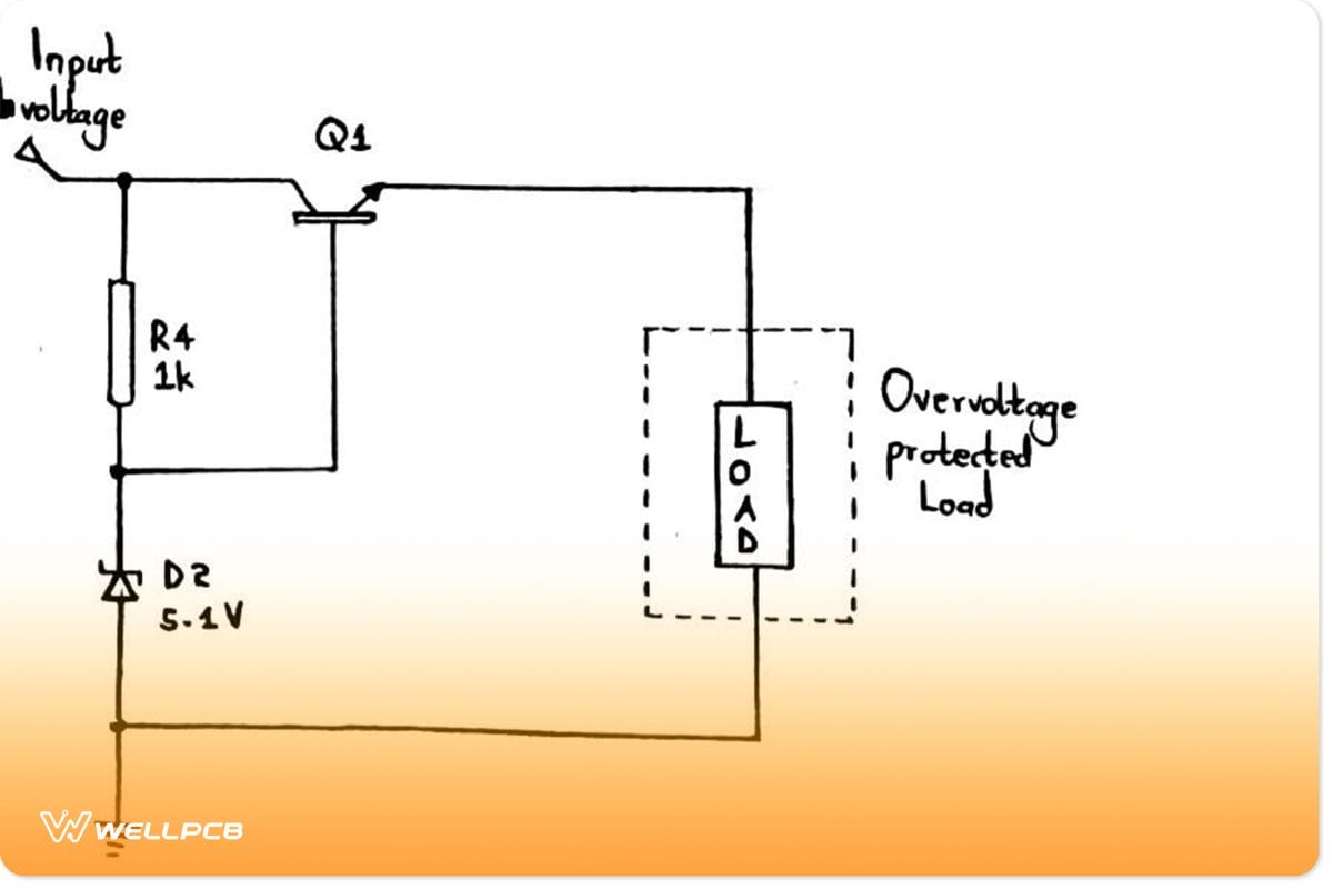
A Zener voltage regulator circuit
For the above circuit, the preset level of the course is the Zener diode rating. So, the circuit can’t conduct at a threshold value of approximately 5.1V.
Preset value: It’s a high threshold voltage that causes the circuit to disconnect the load side supply.
Additionally, the base-emitter voltage of the transistor determines transistor Q1 conduction. As such, when the circuit’s output voltage rises, the transistor’s Vbe (base-emitter voltage) increases, and there’s less conduction. Subsequently, the output voltage reduces and maintains a sustainable voltage level.
Overvoltage protection circuit using Zener diode
This second overvoltage protection circuit will use a PNP transistor alongside the Zener diode.
Finding an exact Zener diode value can be challenging here, so choose a rating that’s close to your preset value.
Component list
Breadboard,
FMMT718 PNP transistor,
Connecting wires,
Resistors (1k, 2.2k, and 6.8k), and
Zener diode 5.1V (1N4740A).
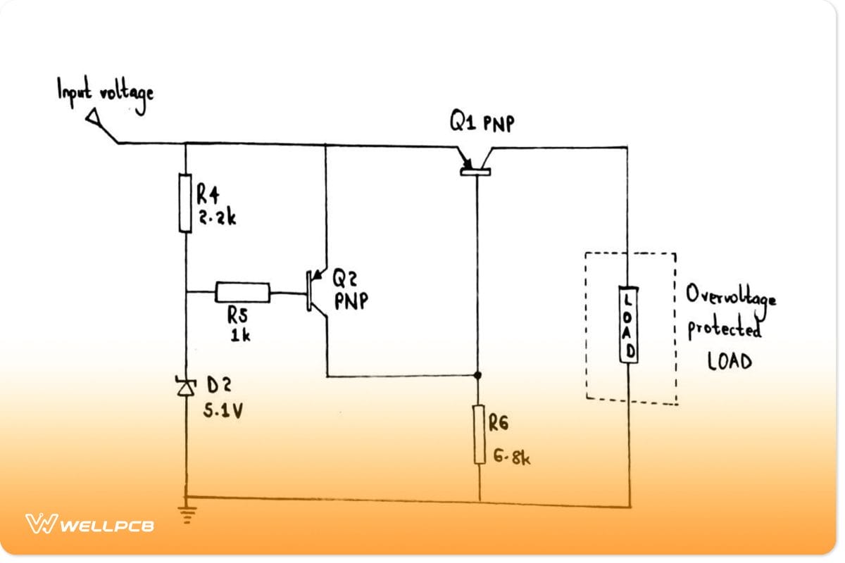
Circuit for overvoltage protection using a Zener diode
Working principle of the over-voltage protection circuit
If the preset level is higher than the voltage in a regular operation, Q2’s base terminal increases. It then turns OFF since it’s the PNP transistor. An OFF condition of Q2 results in the base terminal of Q1 becoming low and allowing current flow.
On the contrary, the Zener diode begins conducting if the preset value is lesser than the voltage. In turn, it turns on the Q2 as it connects the base of Q2 to the ground. In the Q2’S ON condition, the base terminal of Q1 becomes high, and it turns on like an open switch. Thus, Q1 limits the current flow through it, preventing excess voltage from damaging the load.
Further, the voltage drop in the transistors needs to be below to provide an accurate circuit reading. In our case, we’ve used an FMMT718 PNP transistor with a low VCE saturation level. It keeps the drop across the transistors as low as possible.
The disadvantage of the circuit
Power dissipation: dissipates heat, therefore, wasting energy due to the series resistor connected.
Summary
In conclusion, modern power supplies are undeniably reliable in our day-to-day activities. However, chances are, they might fail due to factors like overvoltage. Therefore, it is necessary to have a means of overvoltage protection.
Rest assured, with the comprehensive guide above, your circuits are safe. But still, in case you still have a burning issue, contact us.


