About piezo drive circuit ,Often, we need to measure physical quantities such as temperature, sound pressure, and mechanical stress. A transducer is any device that we can use to measure such quantities. Typically, what a transducer does is convert a mechanical signal into an electrical signal.
Many kinds of transducers exist, and a Piezoelectric transducer is one of them. Any device that uses this transducer can convert a physical quantity into an electric signal. Nonetheless, the million-dollar question is how does a piezoelectric transducer operate?
This piezo drive circuit guide will explain the circuitry of this system and its common design technology.
Contents
1. Piezo Drive Circuit Working Principles

An electrician
You need first to understand the composition of a piezo buzzer. Some materials have piezoelectricity properties, and you will find them in any piezo buzzer. They include quartz, Polyvinylidene difluoride, Lead zirconate titanate (PZT), and Rochelle salt, among many others.
In typical drive circuits, you will find a piezoelectric sounder coated with a conducting material. When you apply sound pressure on the conducting surface, the piezo element’s ions will become active. Consequently, the ions will move from one end of the conducting material to the other.
It will hence lead to the generation of a charge. The output charge will be subsequently crucial in the calibration of the original sound pressure.
Note that this stress can be either tensile or compressive. Thus, the stress type and the orientation of the piezo element will determine the intensity of the output signal.
Besides, note that the audio output will depend on the amount of input AC voltage.
2. Basic Piezo Drive Circuit

Electric Components
You require very few components for this circuit, including an electronic switch, a reset resistor, and a piezo buzzer. You can include a Bipolar Junction Transistor (BJT) or a field-effect transistor (FET) for the switch.
For the circuit, you need a few components, and all are cheap. You can, therefore, work on a small budget. Nonetheless, it has some downsides that include a power dissipation limitation by the reset resistor. Also, your system’s input drive signal will determine the piezoelectric sound quantity. Therefore, you will have to bear with these limitations if you opt for the basic circuit.
Moreover, note that you do not necessarily have to connect the piezo buzzer to the positive terminal. When you connect it to the circuit ground, it will function equally effectively.
3. Adding Buffers to a Basic Piezo Transducer Drive Circuit

A Speaker
You can avoid the problem of the reset resistor in the above circuit by the addition of buffers. For this circuit, you should add two buffer transistors to solve the transducer impedance issue. Nonetheless, this will undoubtedly affect the power delivery of the system. The drive voltage will decrease by approximately 1.2 Volts, but the connection will completely prevent transducer impedance.
Also noteworthy is that you can connect the piezoelectric sounder to the positive or ground terminal. Whichever way you connect it, you will not influence the performance of the sound component.
You can still improve the drive voltage by altering the connection of the theoretical circuit. All you need to do is modify the BJT buffer’s location on the circuit. Alternatively, you can use FET buffers in place of BJT buffers, and the circuit will be equally functional.
4. Half-Bridge and Full-Bridge Drive Circuits
Electric Components
There are many types of driver circuits, but you will not have one as effective as this connection. It is an improvement of the previous circuit and allows a wide range of discrete components. The previous analog driver circuit will strain to deliver, especially when you use discrete components.
You can have half-bridge drivers or full-bridge drivers, depending on your connections. When you use push-pull buffers, this will yield half-bridge buffers. On the other hand, you will create a full-bridge driver when the driver circuit is out of phase. For the full-bridge driver, you can use it by attaching the piezoelectric sounder to the circuit’s output pin.
With full-bridge drivers, you have the advantage of obtaining double the achievable output power of the other circuits. Subsequently, the output sound volume will be higher than that of the basic circuit or half-bridge circuit. You can test this by connecting the three circuits on the same input AC voltage.
Due to the optimum output voltage range, you’ll find these types of driver circuits in electric motors. You will also access the two bridge circuits cheaply. Thus, it is an integrated circuit that you can easily acquire and use.
5. Resonant Driver Circuit
A Circuit board
You can create the resonant driver circuit to power an external drive piezo buzzer instead of the above circuits. You require a discrete inductor, and your system will operate via the parasitic capacitance concept of a basic driver circuit. The resonant circuit operates via a simple principle of energy storage and transfer between the inductor and capacitor.
You can assemble the connection on circuit boards provided that you have these circuit components. The resonant circuit will also be highly advantageous first, given that it is easy to assemble. Secondly, it has electrical efficiency and also guarantees a higher output range than the power supply voltage.

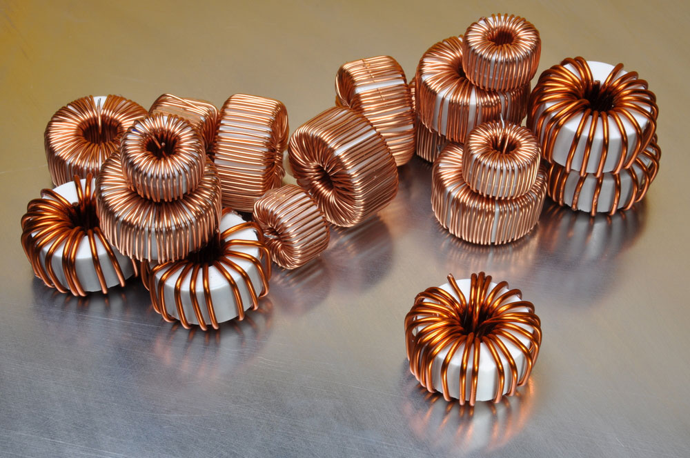
An Inductor
Nonetheless, the resonant circuit will operate only at a constant frequency. Hence, you cannot use it to drive piezoelectric actuators that require a wide frequency range. This constant frequency will also impact the inductor effectiveness. Noteworthy, you can choose an inductor larger or heavier than the common type of circuit parts. It will not in any way affect the audio frequency of the system.
This parasitic capacitance of the transducer will also influence the effectiveness of the system. Many manufacturers do not take care of this aspect; hence you have to put up with it during operation. Lastly, you will also struggle to model the operation mechanism of this system. Thus, you will have to spend more time in the lab during its design phase. Nevertheless, despite these limitations, you will benefit from the high efficiency that it guarantees.
Conclusion
We have given you an elaborate outline of the different piezo drive circuit options. Depending on your intended use, you can therefore choose the one that suits you. All these piezo drive circuits are also easy to assemble. Thus, you can create your desired sound output without much hassle.
In case you want to consult further, reach out to us, and we will respond instantly. We are your all-time aide in electronic matters. Thus, for further insights on electronics, check out other content on our website.


