Contents
What is a Potentiometer?
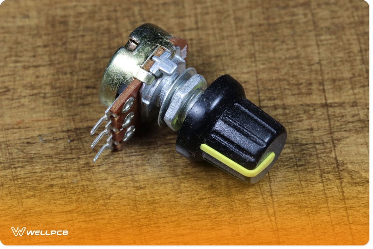
Figure 1: A Potentiometer
A potentiometer is a type of resistor. In a linear potentiometer, turning the device’s shaft changes the resistance. Nonetheless, unlike the conventional resistors whose resistance is fixed, you can alter that of a potentiometer.
Also noteworthy, a potentiometer will feature three pins. Additionally, there is a resistive material, such as carbon, between these pins.
It’s this material that creates resistance. You’ll find this basic structure in all linear taper potentiometers, irrespective of the model.
Also, note that a potentiometer is handy in detecting an electrical instrument’s output signal. Take, for instance, a speaker on the radio.
The device will feature an outer shaft that acts as the volume control knob. Turning this knob changes the variable resistance value. In turn, the electrical signal values will change.
How Does a Potentiometer Work?

Figure 2: Potentiometer, slider, knob, equalizer vector
As mentioned earlier, a potentiometer primarily features three main parts. The two terminals on each end are connected to the strip of resistive material.
Then, there’s the middle terminal that is connected to the wiper.
We can denote the terminals as 1,2 and 3, as illustrated in the circuit diagram below. In this case, 1 and 3 are the terminals connected to the resistive material. On the other hand, 2 is the terminal connected to the wiper.
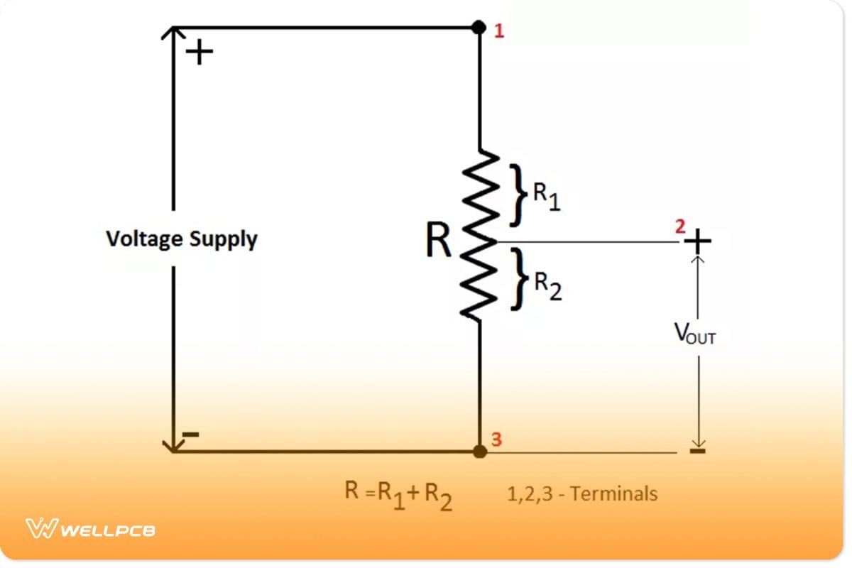
Figure 3: A Potentiometer Circuit Diagram
The wiper divides the resistors into two equal paths from the circuit diagram above. Thus, the resistor with a longer route will exhibit a higher circuit resistance.
Note that in a continuous circuit, the length is a crucial determinant of the resistance of a resistor.
Now, take a case when we have two resistors. We can denote them as R1 and R2. In our case, from the circuit diagram above, the wiper voltage is the voltage close to R2.
Thus, this circuit is now a voltage divider. We can calculate the output voltage of such electric circuits using the circuit equation below.
V (out) = R2R1 + R2V
V, in this case, represents the supply voltage of the circuit. Note that you can alter the output voltage when you shift the position of the wiper closer to terminal 3.
Potentiometer Wiring
The following are the three prominent examples of how to wire a potentiometer.
Wiring Example 1: Variable Resistor
You can create this potentiometer connection when you have a simple resistor. It only requires two pins, including the middle pin and one side pin. Here is the schematic representation:
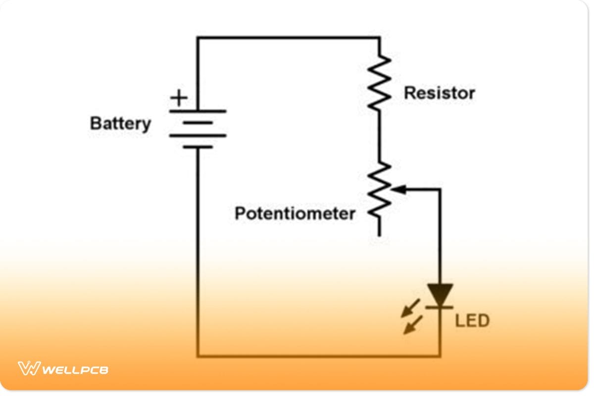
Figure 4: Variable Resistor Wiring
Such a simple circuit will effectively dim an LED. As you can see, there is an extra resistor in the course. Its function is to protect the LED from destruction even when turning the resistance to zero.
During operation, when you turn the knob of the potentiometer to one end, the resistance will increase. Conversely, resistance will decrease when you turn it in the other direction.
Wiring Example #2: Strange Connection
You may come across a connection that resembles this circuit diagram:
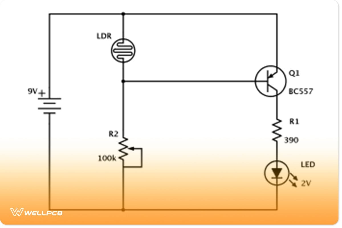
Figure 5: Strange Potentiometer Connection
The bottom and the middle pin are connected, but this does not affect the resistance. Note that while such a connection appears strange, it is not abnormal. It is the same as connecting only two pins.
If you connect a third pin to the wiper terminal pin, it will not influence resistance. You might wonder why some people go for such a bizarre connection. There is no reason behind it, only that some prefer it that way.
Wiring Example 3: Volume Input
Lastly, there is a connection, which is represented here below.
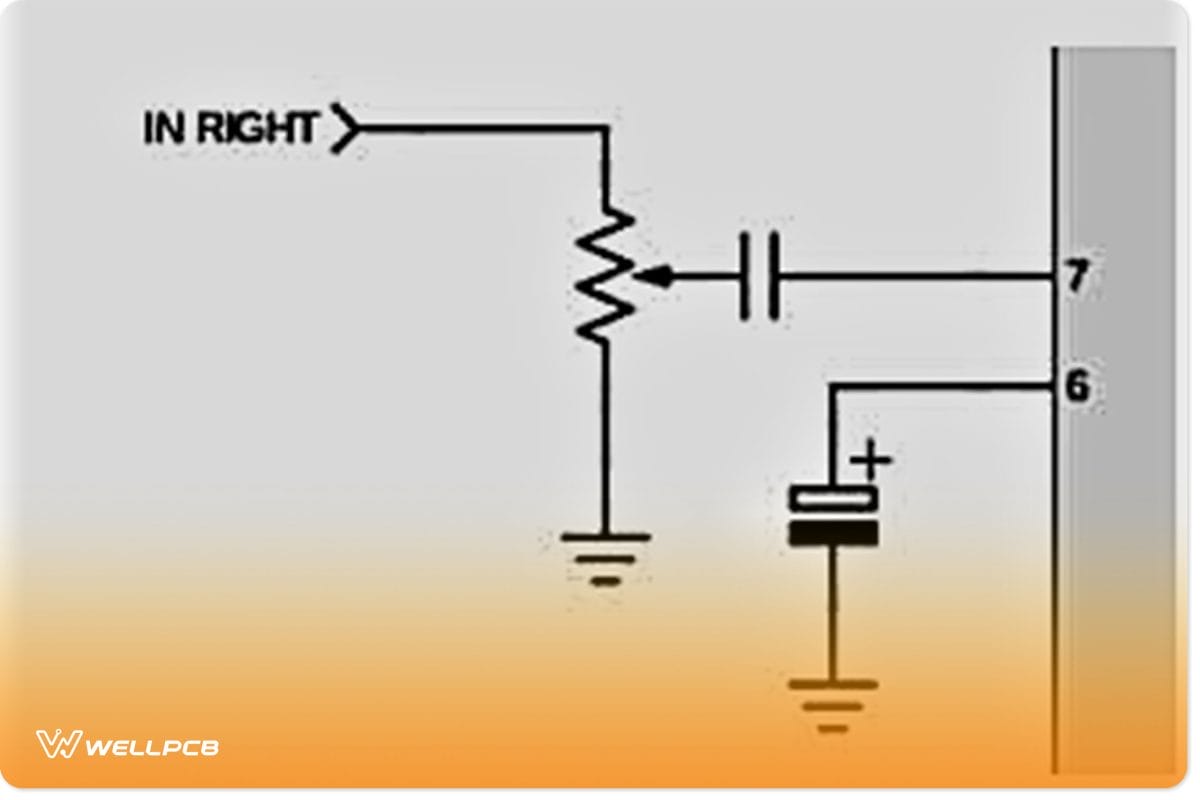
Figure 6: Volume Input Potentiometer Connection
In this connection, the three pins of a potentiometer have been connected. It is a simple connection that is useful in controlling the volume of audio devices such as an amplifier.
Such a connection will create a voltage divider, which will be handy in increasing the input signal voltage.
For instance, say you are using this connection to control an external device such as an audio amplifier. The more you turn the knob, the more you’ll reduce the volume.
As a result, such a connection is commonplace in audio equipment.
How to Wire a Potentiometer?
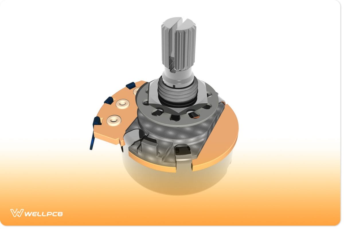
Figure 7: Potentiometer as an electronic control unit
Wiring a Potentiometer is straightforward.
First, you’ll need to ground the first terminal.
Next, you’ll need to supply an input signal to the third terminal.
Finally, apply an output signal to the center terminal.
The following are the critical steps in the wiring process.
Selecting and Preparing a Potentiometer
- First, you need to identify the three terminals on the potentiometer. Next, place the potentiometer on a flat surface. As we mentioned earlier, the first terminal is the ground terminal. On the other hand, the middle terminal is the potentiometer’s input port. Lastly, the third terminal is the output port.
- Next, you need to know the resistance ranges that a particular potentiometer can control. Most potentiometers will not control high voltages. Thus, make sure to read the resistance that the particular potentiometer can deliver. For instance, you may have a potentiometer with a rating of 200K. It means that it can supply resistance of up to 200,000 ohms.
- During wiring, it’s imperative to place the potentiometer on a flat surface. Make sure the potentiometer’s terminals are facing you. Next, make sure that you have removed the backside of the electrical system that you want to connect. It’ll expose the input and output terminals which are essential in making the connection.
- Next, you’ll need to strip the sections you want to use during the connection. A wire stripper will be handy in this process. Also, you’ll require a soldering wire to join the system’s terminals. When stripping the wire, ensure that you remove approximately 1.3 to 2.5 cm from the top section of the wire. Note that some electrical components require specific types of soldering wires. Thus, make sure you select the right types.
Soldering Your Terminals
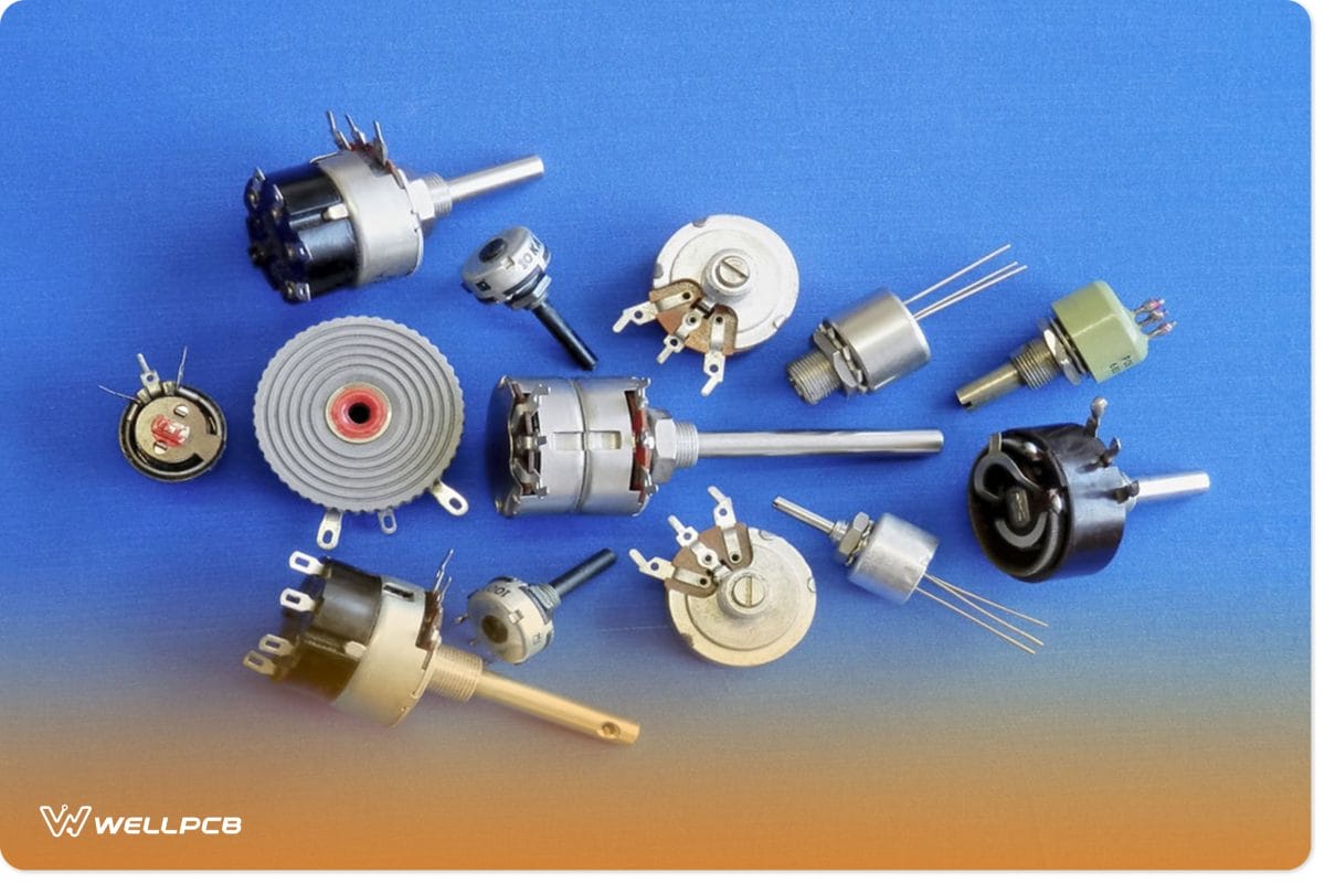
Figure 8: Regulatory knobs in various versions.
- You will require soldering the wire to the potentiometer and the electrical component on the other end. First, place the wire on the part you want to attach it to. Next, place a soldering flux and the soldering iron and press. Start with the first terminal, which is the ground.
- Next, you need to solder a wire to the middle part of the potentiometer. Remember, the center part is the input of the potentiometer.
- Lastly, solder a wire to the third terminal on the potentiometer. It is the output terminal of the potentiometer. Thus, this is the terminal that you’ll connect to the output device. Hence, on a guitar, the output terminal of the potentiometer will be on the input jack. Similarly, on an audio amplifier, it’ll be the input channel of an audio amplifier.
Using Your Potentiometer

Figure 9: Color Sliders Illustrating the Working of a Potentiometer
- Also, you need to check if the potentiometer is functional. First, connect the output and input terminals of the potentiometer to the voltmeter’s probes. Next, turn the potentiometer’s knob to alter the voltage. The signal should increase/decrease when you turn the knob. If it doesn’t change, you have wired the potentiometer wrongly.
- Next, connect the potentiometer to an output device such as a guitar. Turn the knob to determine if there is a change in the note of the system. If there is a variation, the potentiometer is operational.
Conclusion
As you have seen, a potentiometer is a resistor with varied resistances. We have expounded on its working principle and how to wire it.
With these insights, you can now use a potentiometer for your college or DIY project without any hitch. Nonetheless, if you want to clarify, talk to us.
We’ll respond to your queries promptly.
