
Contents
Fading and Pulsing LED using 555
The pulsing or fading LED circuit is a small and easy project that allows you to control LED pulsates or fades with a 555 timer IC.
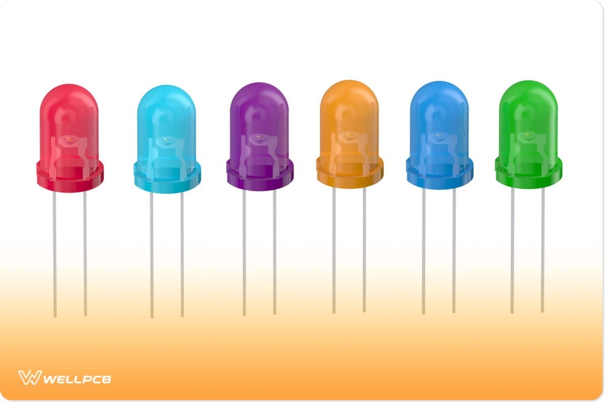
LED
Interestingly, you can achieve two types of fade effects with this circuit.
These include the fade-out fade-in and the fade-in fade-out effects.
Also, you can use this simple circuit for building decorative lights or simple pulsating LED strips.

So, let’s take a closer look at how this circuit works.
How Does it Work?
The 555 timer IC is the equivalent of a heart in this circuit. So, with the 555 timer IC and a transistor, you can run most circuit operations—coupled with a few resistors and capacitors.
For this circuit, the timer IC works in a stable multivibrator mode and creates time pulses that control how the LED fades in and out.
The resistors also help you determine the delay when the LED fades in and out. But that’s not all. The capacitor also plays a vital role in the fading of the LEDs.
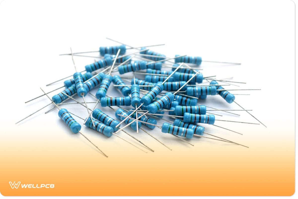
Resistors
Also, the transistors amplify the signals moving to the LEDs to a level enough to light them up—without damaging them.
Moreover, this circuit’s operating voltage ranges between 9v and 12v. Your LED with a current rating of 25mA will be compatible with this circuit.
Note: You can add more LEDs to your circuits by connecting them with a resistor in parallel.
Circuit Diagram
Here’s the diagram and schematic of the circuit we’ll learn to build.
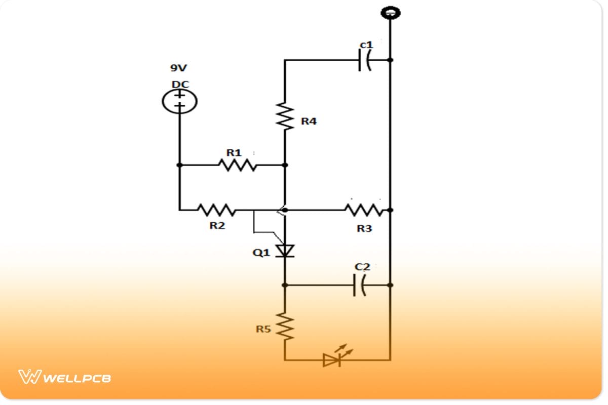
Circuit Diagram
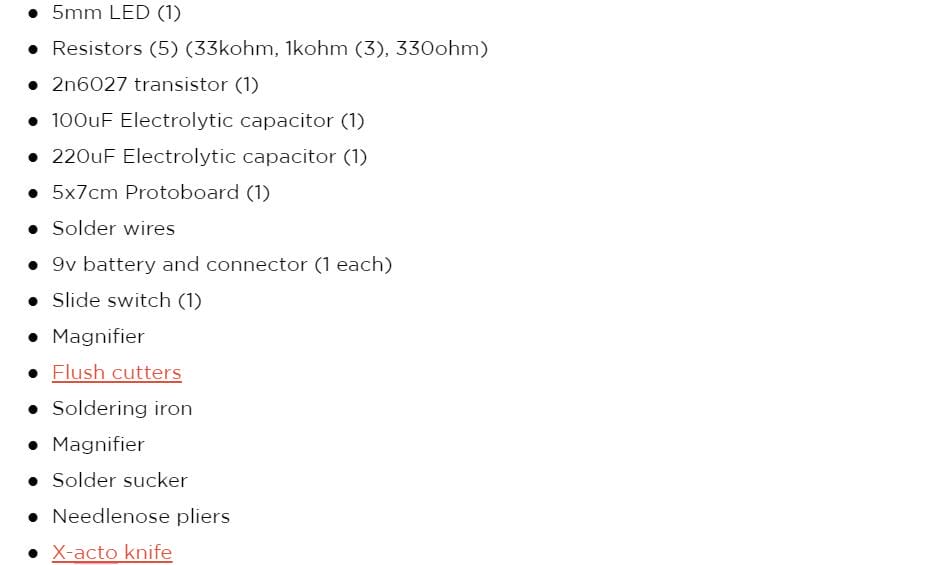
Components Needed
To build this circuit, you’ll need the following components and tools:
How to Build
Now, we’ll walk you through the step-by-step method for producing a perfect and working pulse or fade LED circuit.
Step 1: Gather and Inspect Your Components
First, ensure you have all the necessary components and tools. Also, check if your details are working correctly.
Then, check your capacitor voltage to see if you have a bad capacitor or resistor. To avoid errors, ensure that you replace any faulty one before you start building.
Step 2: Build Your Circuit Board
Then, the next step is to assemble your circuit board.
Also, if you can’t read schematics, we’ve added both the circuit schematic and diagram side by side above so you know where and how to place your components.
Step 3: Solder your Switch and Resistors
You can start building your circuit by soldering your switch to the circuit board. We recommend soldering it to the edge of the board. Also, don’t forget to leave a hole in your board for your 9v battery.
Note: when soldering, make sure it looks like a mini volcano. If it doesn’t, you’ll likely have a cold joint. Also, make sure you heat the lead first before adding the solder.
Once you’ve soldered your switch, add your resistors to the board. Also, bend the resistor leads to prevent them from falling out.
Now, solder the first 1K resistor by pressing it flush to the board and soldering to make a connection. Next, do the same for the other resistors in this order: 33k, 1k, 1k, and 330-ohm resistors.
Note: don’t cut off the excess leads yet. They’re still vital if you want to make connections without wire later.
Step 4: Solder Your Transistor and Capacitors
Next, place your transistor according to the circuit diagram, which should be in front of the three resistors you soldered in the middle.
Also, orientation is essential to ensure the transistor’s flat side faces the resistors. Then, adjust the leads to get the position and proceed to solder.
After this, add your capacitors to the circuits according to the diagram.
Don’t worry if you use too much solder. You can use your solder sucker to remove all excess solder from your circuit.
Step 5: Make Your Connections
First, solder the 1k resistor closest to the switch to the positive lead of the 100uF capacitor. Next, we recommend bending the tip of the resistor towards the side of the capacitor. Once you’ve made the connection, you can remove the excess leads—if any.
Next, take the transistor’s lead closer to the 100uF capacitor and connect it to the 1k and 33k resistors, creating an L-shaped joint.
Also, take the middle lead of the transistor and connect it to the mid-1k resistor. After running these connections, cut off the excess leads.
Check the 220uF capacitor and connect the positive part to the transistor; the negative leads to the negative charge of the 100uF capacitor.
For the bottom half, join the 220uF capacitor’s negative lead to the closest 1K resistor lead, but don’t cut off the extra charges.
When you know your connections, you can add your LED to the circuit. Afterward, you can connect the lead of the 330-ohm resistor to the LED’s positive terminal and solder the LED’s negative terminal to the remaining 1k resistor leads. Still, take that connection and solder it to the battery’s positive terminal.
Step 6: Finalizing
After concluding the setup, there should be two resistor leads without connections: the 1K and the 33K. You’ll have to create a solder bridge to build a strong bond between the resistors.
Afterward, you can cut off the lead of the 1k resistor. First, however, keep the 33k resistor’s information and connect it to the battery’s positive terminal, and as usual, cut off the excess leads.
Note: don’t throw away your excess leads. They come in handy when you want to make a connection without wires.
Make sure you don’t connect the information of the outer switch so you can turn your circuit on and off without having to remove the battery.
Final Thoughts
Building a pulsing LED circuit is fun and easy because of its basic electronics. Once you’ve set everything up with all connections, you must test the circuit.
However, you should cross-check your circuit and connections before testing. This will protect your battery or components from damage.
If you have a lot of blobs from using too much solder, don’t worry about it. Clean up, and your circuit will be alright.
If you found this project interesting and would like to ask more questions, feel free to contact us. We will be happy to help.


