The Raspberry Pi is an essential microcontroller in robot electronics projects. It is primarily thanks to its compatibility with other peripherals like audio jack, lights, and sensors. In this article, we’ll discuss the features of the raspberry GPIO pinout at length.
Contents
Get to Know the GPIO Pins
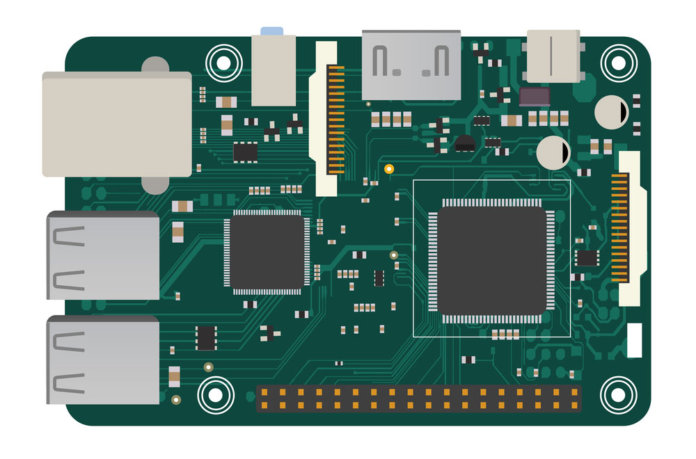
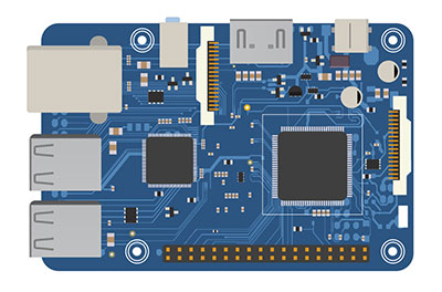
Fig 1: A Raspberry Pi DIY electronic board
Generally, a GPIO header pin is a digital converter, and it can be either in the on or off state. Here is a complete list of the key pins:
5V pins
They are output pins useful in providing a 5V supply output from the Raspberry Pi. Often, these are PINs 2 and 4.
3.3V pins
Their primary function is to deliver a 3.3V power supply to the Raspberry Pi’s external components. You’ll find them represented as pins 1 and 17.
GND Ground pins
Ground connections are often near the electric circuits to protect the Raspberry Pi’s board from burning. Besides, it is from the ground that you can measure the electrical circuit’s voltage. The ground connection GPIO header pins include 39, 34, 30, 25, 20, 14, 9, and 6.
Reserved Pins
They are essential in enabling alternative functions, specifically, the communication of the EEPROM and I2C. However, if you are not well conversant with the operation of the Raspberry Pi, do not connect any appliance to them. The alternate function GPIO pins for reserved purposes include pins 27 and 28.
Various Functions Performed by the GPIO pins.
Fig 2: GPIO with Electronic components on integrated circuit board Background
Pulse Width Modulation (PWM)
GPIO pins are imperative in pulse width modulation, converting digital signals to analog signals. All pins can be useful in software PWM, but for hardware PWM, only pins 12, 13,18, and 19 are essential.
Serial Peripheral Interface Pins on Raspberry Pi 4
Serial Peripheral Interface (SPI) is essential in facilitating communication between devices and the Raspberry Pi. Examples of the devices include actuators and sensors.
Essentially, the Raspberry Pi communicates via the master-slave bus protocol. It includes the Master Out Slave Pin (MOSI) and the Master In Slave Out (MISO) pin. The former is handy in sending data to an external device, while the latter helps receive data from external devices.
Also, note that the serial port makes it imperative to use at least 5 GPIO ports, primarily for MISO, MOSI, GND, CE, and SCLK. In this case, the CE serial port pin enables or disables circuit integration. On the other hand, the SCLK fulfills the clock roles in SPI communication.
Inter-Integrated Circuit Pins on Raspberry Pi 4
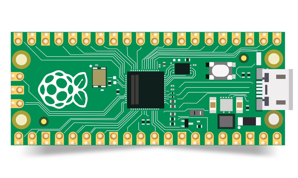
Fig 3: Raspberry Pi Pico
You can also use the Inter-Integrated Circuit (I2C) chipset GPIO pins to control the peripheral devices on the Raspberry Pi model. Other essential pins include the Serial Clock (SCL) and the Serial Data (SDA) GPIO ports. The other type of data you can send is the erasable programmable read-only memory (EEPROM).
For data transfer via SDA, you’ll use Raspberry Pi GPIO connector pin 2. Also, for data speed control, you’ll use the GPIO 3 physical pin, which in this case will function as an SCL GPIO connector. On the other hand, you’ll use the GPIO connector pin 0 for data transfer from Pi’s GPIO hardware for EEPROM.
Lastly, the GPIO connector pin one functions as the additional GPIO pin for data speed control.
UART Pins on Raspberry Pi 4
In UART- Universal Asynchronous Receiver Transmitter, there’s sequential bit-by-bit data transmission. For this transmission, a transmitter and receiver are necessary. The GPIO pins accessible for these functions are GPIO 14 & 15. The former is the transmitter, while the latter acts as the receiver.

How to get the Pinout to run the Raspberry Pi?
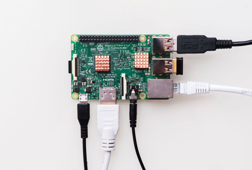
Fig 4: Raspberry pi single board
First, you need to know the Raspberry Pi GPIO version you’re using to understand the Pinout. The complete list of different versions includes Raspberry Pi 1, 2, 3, and 4.
Raspberry Pi 1
The initial Raspberry Pi version has a 26-pin GPIO header. However, the second revision of the Raspberry Pi GPIO 1 is different in the GPIO ports numbering. It is because Raspberry changed its CPU to cater to alternative functions.
The main difference is the BCM numbering of the I2C pins, which Raspberry changed from 0 to 2 and 1 to 3.
Raspberry Pi 2, 3, 4
All add-on boards have a 40-pin GPIO header. Also, Raspberry Pi 2 and Raspberry Raspberry are similar regarding the first 26 pins.
However, Raspberry 2 and subsequent versions have additional GPIO pins to improve functionality. For instance, the additional 24 pins facilitate serial protocols like I2C and SPI.
Lastly, color codes, signal names, and SPI bus pin names help identify the respective GPIO hardware parts. Hence, consider checking these coding as they’ll help configure remote GPIO for Raspberry.
Conclusion
The Raspberry Pi is a valuable production board/adapter board because of its extensive list of chipset GPIO pins. We’ve explained some critical pins for any GPIO driver model. For further questions, communicate with us, and we’ll help promptly.


