Contents
What is the Relay Drive?
Briefly, a relay is a switch with an electric operation. A relay driver circuit is a circuit type that runs a relay, therefore contributing to an appropriate circuit function. In turn, the relay switch opens or closes as per the circuit requirement and functions.
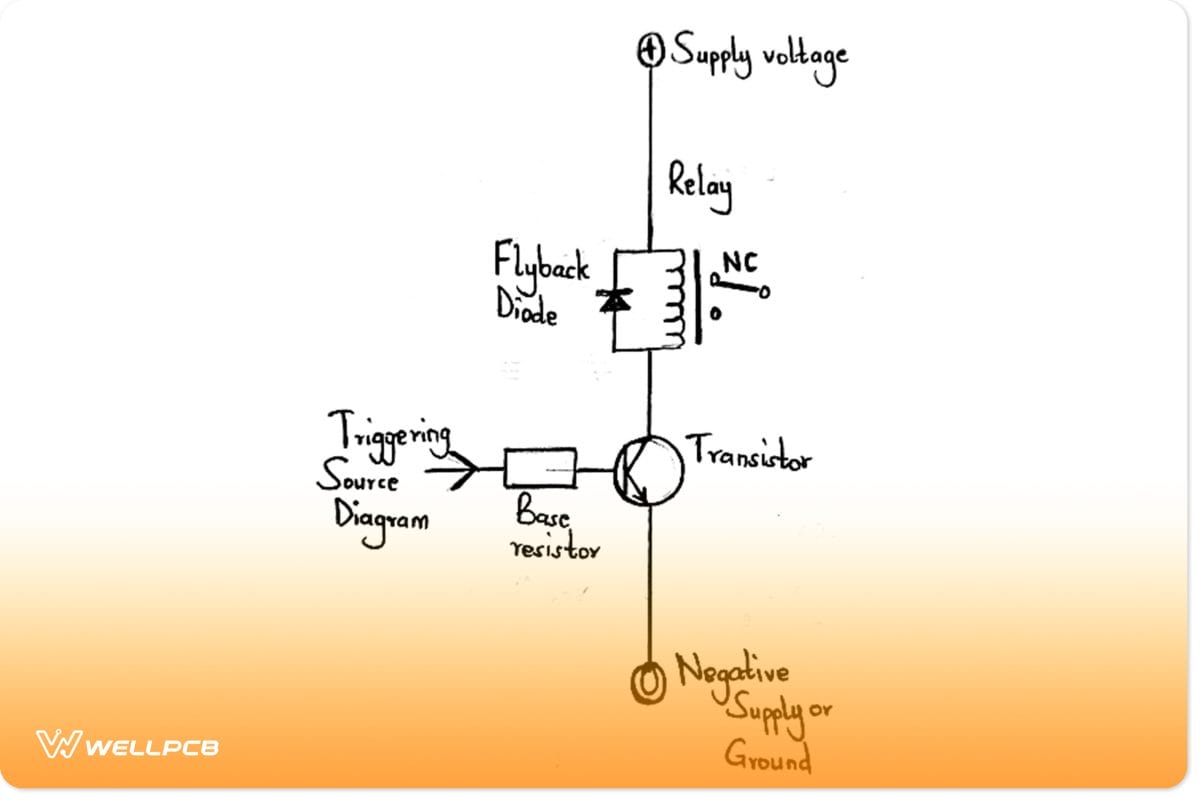
Example of a relay driver circuit
How does DRIVE work?
Working principle
Let us go through the points below to understand the working principle of a relay drive.
- A relay structure comprises a spring-loaded contact and coil that move undisturbed across a pivoted axis.
- The central pole ensures that as the relay coil receives voltage, it joins the N/C contact (Normally Closed). The connection happens because the relay coil has an electromagnetic pull that attracts the pole iron.
- Later, when you switch OFF the relay coil, the central pole disconnects from the Normally Open (N/O) terminal. It then joins the N/C switch contact terminal, hence being in a default contact position.
Generally, the switch OFF and switch ON operations in a relay drive alternately switch N/C to N/O. And it majorly depends on the state of the relay coil.
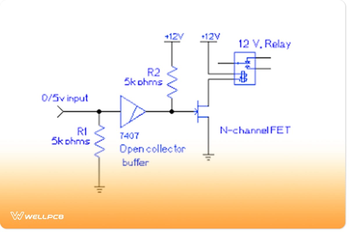
Circuit diagram of a functional drive
Design the Calculation Formula for the Relay Driver Circuit
The expression below gives the formula for calculating a transistor’s base resistor.
R = (Us – 0.6) hFE/Relay coil current
Whereby;
R is the transistor’s base resistor,
Us is trigger voltage/source to the base resistor and
have is forward current gain.
Use another Ohm’s law formula to get the relay current: I = Us/R. Here;
I = required relay current
Us = supply voltage
How to Build a Relay Driver Circuit
A few points to note on the relay drive circuitry are;
- Use 2N4401 for low-power relays.
- Then, a Darlington driver is an ideal choice for less base current or high-power relays.
- In addition, ULN2003 suits several relays or loads to drive.
- Lastly, enhancement mode MOSFET fits the relay driving by a CMOS logic.
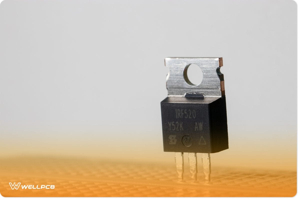
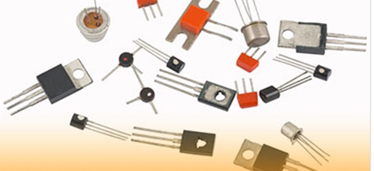
A power MOSFET
Pin arrangement of a relay drive
The pin configuration of relay driver circuits depends on the manufacturer. Therefore, it is advisable to check the datasheet for accurate information.
But generally, most have the arrangement below;
NO = When the relay coil gets energized, it connects to the common terminal and remains open throughout.
NC = When the relay coil gets de-energized, it comes in contact with a common terminal. It’s also always connected.
The third contact pinout is the central pole.
An AC Relay Driver Circuit
A relay driver circuit runs on AC power. For that reason, we’ll only need a transient suppressor and sufficient AC voltage as rated for the relay.
And instead of diodes to eliminate voltage spikes, we’ll use them to alternate half-cycles. Also, we won’t connect diodes in reverse parallel to create a functional transient voltage suppressor. Instead, we’ll use an RC series network and secure it parallel across the coil. Moreover, the resistors regulate the discharge as the capacitor absorbs excess charge.
Components needed for preparation
- 0.05µF capacitor
- AC voltage source
- AC relay
- 100Ω resistor
Precaution: Handle with great care the AC power that comes directly from a wall outlet to prevent shock.
Circuit Diagram
The diagram below is the final product we’ll have after our AC relay driver circuit assembly.
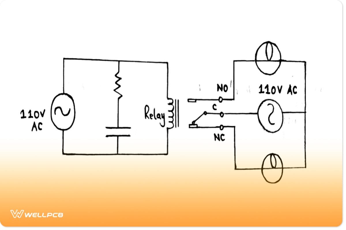
Circuit diagram of an AC relay driver circuit
We only feed the AC relay with an AC voltage of its rating. For example, for a rated relay voltage of 110VAC, we’ll need 110V from the AC power source.
The resistor and capacitor in series suppress voltage spikes by acting as the transient voltage suppressors. Therefore, that side of the circuit operates as our relay driver. Finally, when the relay receives enough power, it turns on and then powers the load it’s in connection with instantaneously.
A DC relay driver circuit
You’ll use components like the Zener diode for DC relay circuits to eliminate voltage spikes as the drive closes/opens. In other words, the diode acts as a transient voltage suppressor. The relay coils function as inductors.
Component to prepare
- Zener diode
- DC voltage source/ DC power sources such as wall-wart power and batteries.
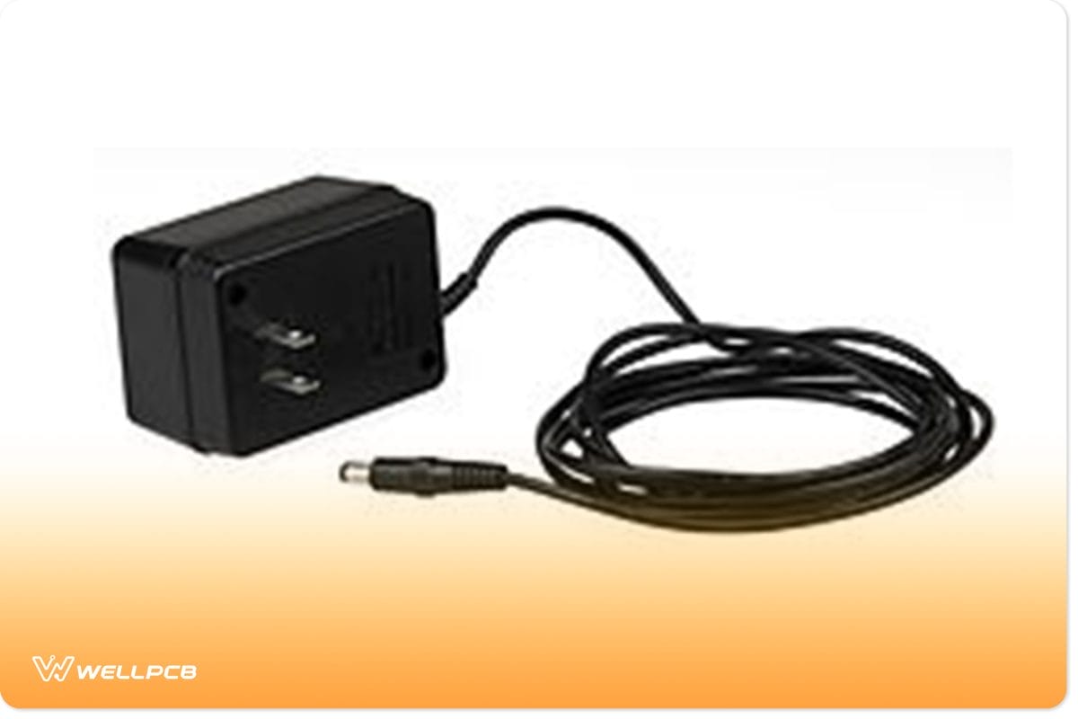
A Wall-wart adapter
- DC relay with its rated DC voltage value.
Circuit diagram

Circuit diagram of a DC relay driver circuit
The relay we’re using today has a 9V rating. Therefore, a 9-volt DC voltage source is suitable for feeding the resistor. We also place a reverse-biased Zener diode in parallel to our drive. In that way, once the voltage reaches a specific threshold, the circuit will shunt excess power to the ground. Contrarily, if it gets to the breakdown voltage, it will permit electric flow by conducting.
Ultimately, when there’s sufficient power, the relay closes and drives the output loads.
Using an NPN transistor to build a relay switch circuit
Electronic projects on relay driver circuits often use MOSFETs and NPN transistors as their primary switching devices. It’s because transistors can swiftly provide DC switching (OFF/ON) control of relay coils from several input sources.
Components needed
- Resistor – 1K
- Capacitor – 470µF
- NPN transistor – BC 548
- LED indicators
- IN4007 diode
Circuit diagram
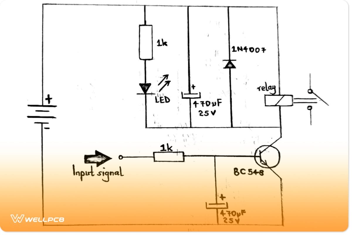
A relay circuit diagram with an NPN transistor
Advantages and Applications of Relay Drive
The pros of a relay drive include;
- First, it uses inexpensive NPN drive transistors that are also commonly available.
- It has fewer components.
- Further, you can easily interface it to a low voltage logic circuitry and a relay economy feature.
- Also, its manufacture has an industry-standard technique.
- In addition, it has several interface options, such as the ULN2003 driver.
- Lastly, you can source the relay power by a higher, unregulated voltage. In that way, there’s load reduction on the voltage regulator.
Applications include:
- Heaters,
- Motors, and
- Lamps.
Conclusion
All in all, relay driver circuits help in switching connected loads in electronic systems with ease. YoYou’llostly applies the drive when you need to control several courses by a single signal. Also, you can use a relay to regulate one circuit by one low-power signal. Hence, knowing how to make the relay circuit on your own can be lifesaving for your operations. The examples we’ve given should broadly help you.
Nonetheless, if you still have any questions concerning a relay drive circuit, kindly reach out to us.