Contents
- 1 How to series connect resistors
- 2 Resistors in Parallel Connection
- 3 Combination of Resistors in Series and Parallel Connection
- 3.1 Resistor Circuit Diagrams– How to combine resistors in series and parallel
- 3.2 Resistor Circuit Diagrams– Current and power in the combination of series and parallel resistor circuits
- 3.3 Resistor Circuit Diagrams– Effective resistance in series and parallel circuits
- 3.4 Resistor Circuit Diagrams–Example application
- 4 Summary
How to series connect resistors
Resistors in series connections have two or more resistors connected end-to-end with the same voltage.
Connect the ends of each resistor to a power output source, assuming wires have negligible resistance. The resistors are in series, so if one has resistance R1, the other resistor also has resistance R2. The total resistance is the sum of the individual resistor’s value; in this case, we use Ohm’s Law for calculation.
Ohm’s law in series resistance circuits
Ohm’s law states that current is directly proportional to the voltage across two points of any conductor. In our case, resistors.
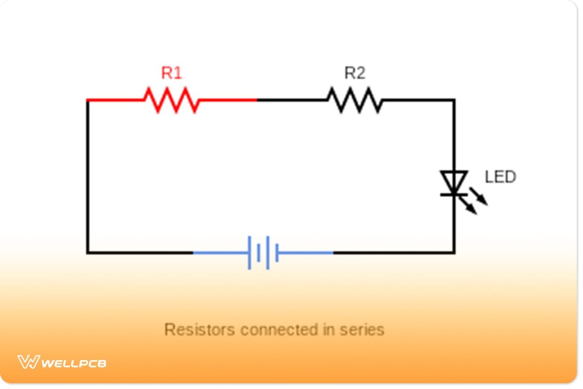
In the diagram below, we have a simple circuit with a series of connections of resistors. The first resistor has a resistance value of R1, and the second resistor has R2.
According to Ohm’s Law, V=IR
V = I * R_t
Where R_t here is our effective resistance of resistors connected in the circuit, the source voltage (V) across the resistor circuit is the same as the voltage. Moreover, the resistors are in series, so they have the same potential drop. We can use Ohm’s Law to find this value as well.
Current and power in series circuits
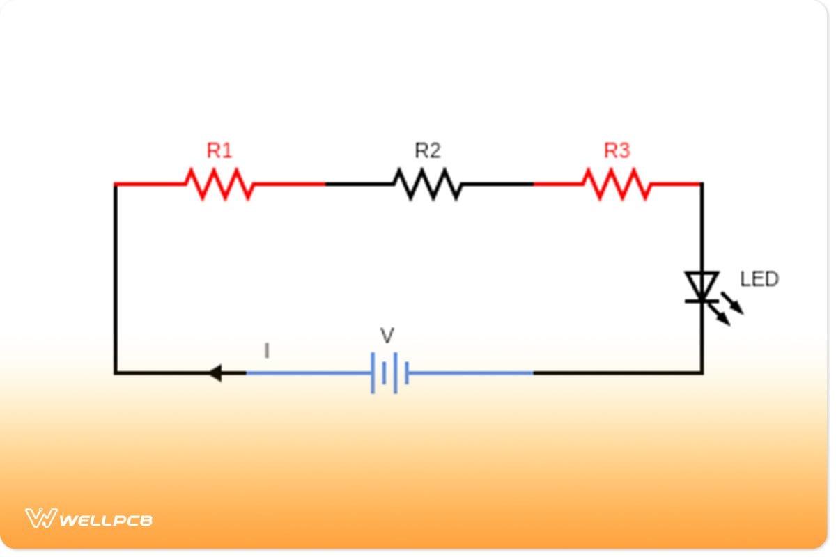
(Series resistor circuit)
In a series resistor circuit, the total current (I) is the same between all resistors. That is to say, the current that runs through resistor_1 is the same Current that will flow through resistor_2. Also, the current output is equal to that provided by the battery. Significantly, if you add more resistors to the circuit, the present value reduces across the course. This is because resistors are equally sharing the current amount despite their difference in resistances.
So, current; I_t = I_1=I_2.
Similarly, Current, I am also =V/Rt
In other words, applied battery voltage(V), divided by effective resistance(Rt).
Power is given by the formula; P=V*I
In a series circuit, the potential difference applied is the total sum of individual voltages across each resistor.
Therefore, when calculating electric power, P=V_total*I_total
Effective resistance in a series circuit
The equivalent resistance is the amount of resistance that a single resistor would need to equal the overall effect of the collection of resistors present in the course.
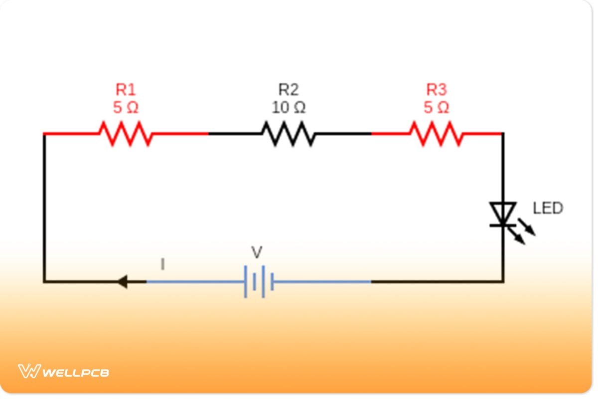
In a simple series circuit, the total resistance is equal to the sum of the individual resistor’s value. To clarify, add up the resistor values. But, the resistors also have the same potential drop. For example, in the circuit above, the effective resistance equation is given as follows;
Rtotal = R1 + R2 + R3
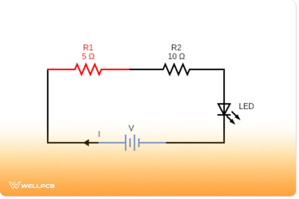
R_t = 5Ω+ 10Ω+ 5Ω= 20Ω
Example application
Led Current Limiting
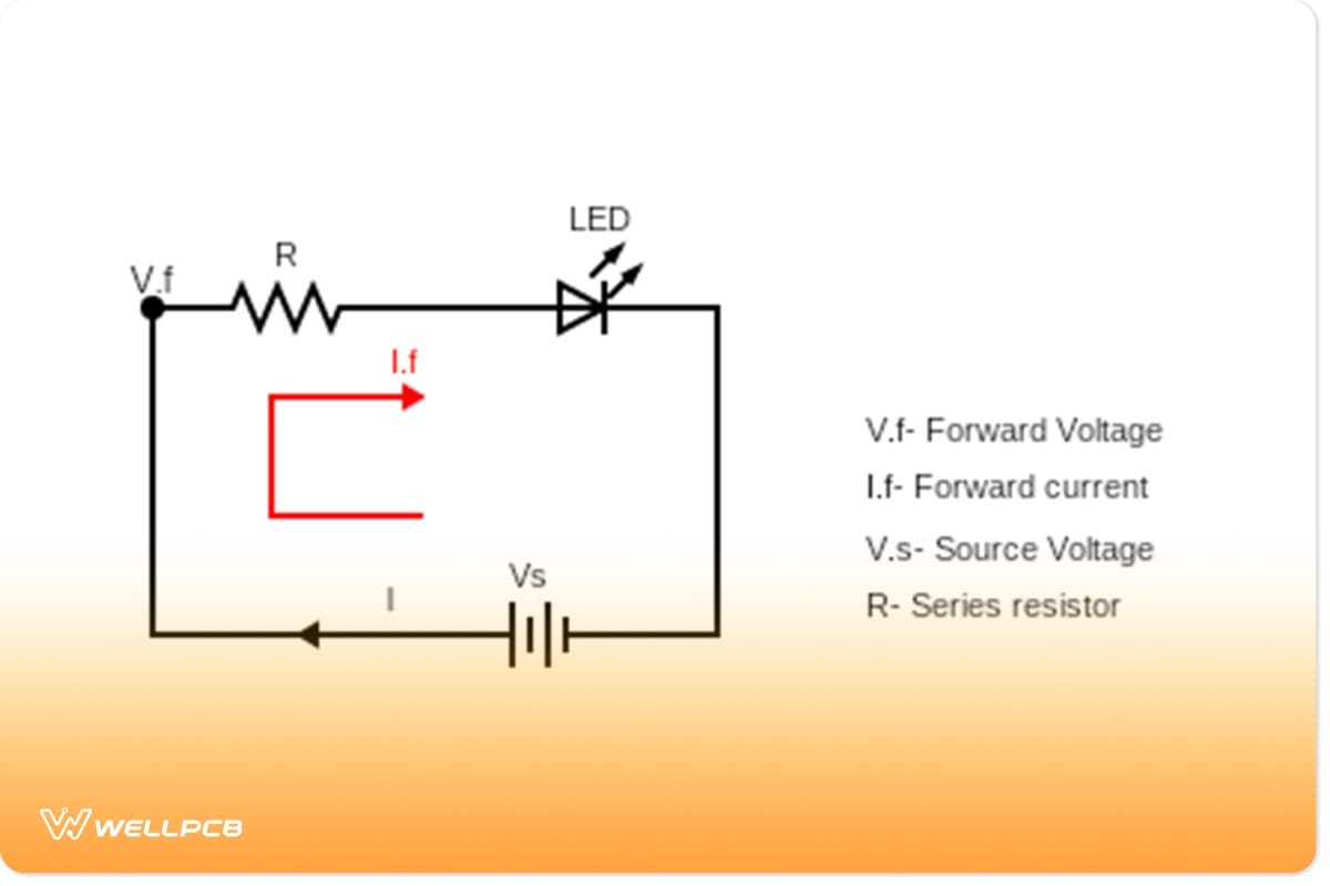
(Led Current Limiting Circuit Diagram)
LEDs have different current ratings; therefore, each needs a Current equal to or less than its rating. Otherwise, they will be damaged or destroyed if there is too much current flow through the circuit. It is dangerous and can result in component damage or, worse, a fire! Therefore, it’s best to use a series resistors connection to protect your electrical circuits. The series resistor limits the maximum voltage drop across the LED, which keeps it running within its safe operating conditions!
Resistors in Parallel Connection
For resistors in parallel connection, one end of all resistors gets attached through a standard wire. Similarly, all the other ends connect through a standard wire.
How to parallel connect resistors
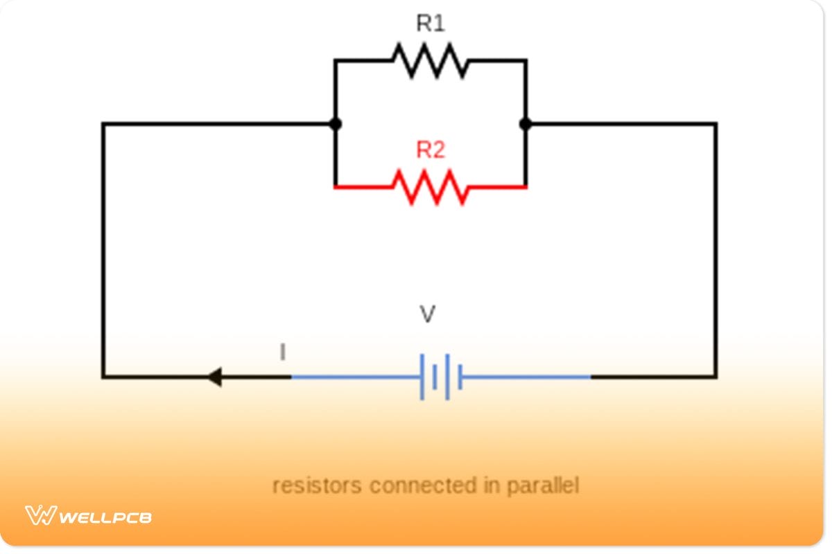
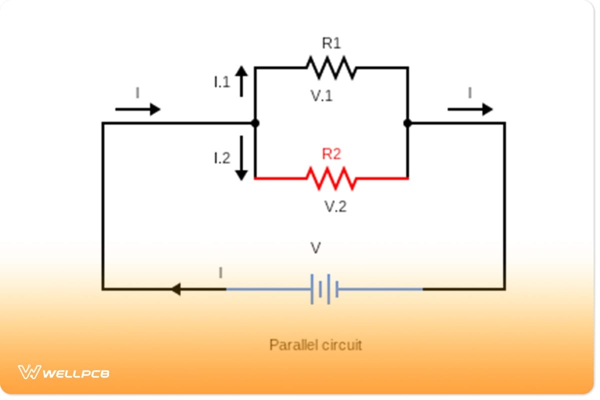
(Diagram of resistors connected in parallel)
In the above example, we have a simple circuit with a parallel connection of resistors.
Connecting resistors in parallel are different because each resistor’s ends are not connected to a power source, and instead, they share one point as their shared connection.
Also, assume wires have negligible resistance.
Resistor Circuit Diagrams– Ohm’s law in parallel resistance circuit
We use Ohm’s law to find the individual Current that flows through each resistor in parallel. This is because the potential drop is equal across each resistor.
In a case where the output voltage is constant across each resistor, current I=V/R
Resistor Circuit Diagrams– Current and power in parallel circuits
For resistors in a parallel configuration circuit, the voltage drop across parallel branches is the same. Also, the current flowing throughout the circuit is the same as the sum of individual Currents flowing through each resistor.
However, if you add more resistors to the circuit, the overall resistance of the circuit decreases.
(Current splitting in parallel connection)
Since the total Current shared gets divided across each resistor.
So, apply the current equation I_t=I_1+I_2
That is to say, the total current flowing in the circuit is equal to added split currents flowing through resistors.
The total power dissipated by the resistors is found using P=VI. Where I is the total current in amps, and V is the voltage across each resistor in parallel.
Resistors with the most significant resistance receive the lowest Current, while resistors with the most little individual resistance get the most excellent Current.
Therefore; P=VI
P = (I_1 + I_2) * V
So, for each resistor, Resistor R_1 I1= V1/R1. Resistor R_2 I2= V2/R2
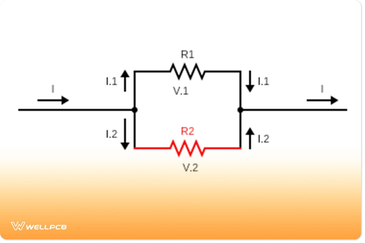
Effective resistance in a parallel circuit
The diagram below helps to explain how to find effective resistance in a parallel circuit.
(Schematic diagram explaining effective resistance)
To calculate equivalent resistance, we need to understand the junction rule as per Kirchhoff’s loop law.
The total resistance in a parallel configuration circuit is the inverse of the sum of all inverse resistances. That is to say, if you have two resistors in a parallel connection, practical resistance calculation becomes;
Circuit equations are as follows;
Since the current splits at a junction, according to the loop rule, then I=I1+I2
And, since V=I1R1 and I1R1=I2R2
Then, Current, I =I_1+ I_2
=V1/R1+ V2/R2
But V is the same =V/R1+ V/R2
= V[ 1/R1+ 1/R2] =V/Req
1/Req= 1/R1+ 1/R2
Also, Eq Resistance Req=[1/R1+ 1/R2]⁻¹
Combination of Resistors in Series and Parallel Connection
In a combination of resistors, some resistors are in a series configuration while others are in parallel structures.
Most importantly, these are more complex circuits to understand. The central concept of finding resistance in combination circuits is transforming the entire course into a series connection circuit.
It is quickly done by applying equivalent resistance understanding in a parallel circuit to the whole combined circuit.
Resistor Circuit Diagrams– How to combine resistors in series and parallel
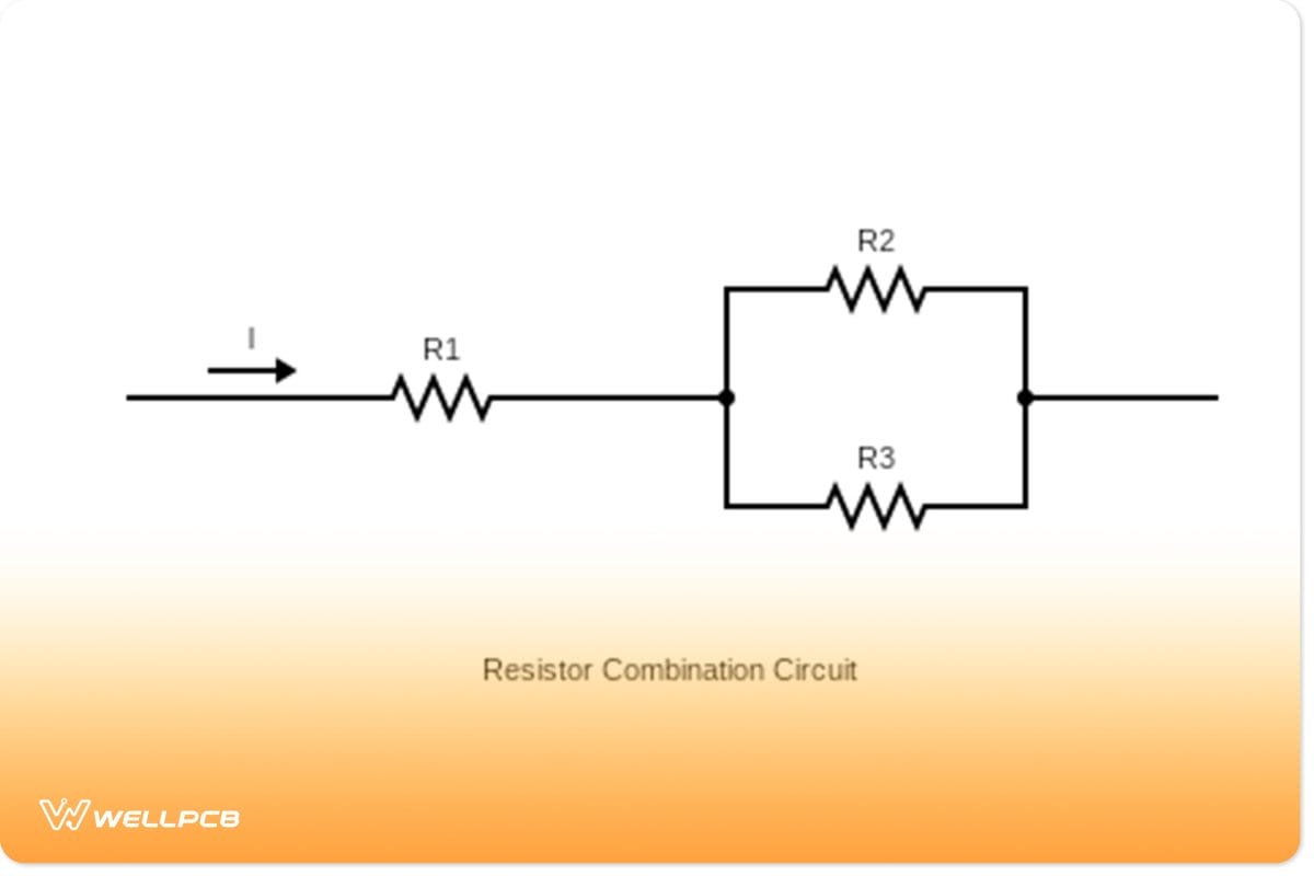
(Resistor combination circuit)
Combining resistors in series and parallel is pretty simple.
First, all you have to do is connect R2&R3 in parallel. Then, click the ends of each resistor to create a node.
Now, add another resistor, R1, to the connecting node, like in the diagram above.
Finally, connect the wire ends to a power source. The total resistance is the sum of each resistor’s value; in this case, use Ohm’s Law for calculations.
Resistor Circuit Diagrams– Current and power in the combination of series and parallel resistor circuits
The total Current is the sum of all individual currents, and so is the power. If several resistors are in parallel, then they will share a common output voltage source.
Importantly, this is assuming it has negligible internal resistance. It also means that the voltage across each resistor will be less than if it was in series.
(Resistors in series and parallel)
If you have combinations of resistors in both series and parallel, you will have to use a variety of voltage and current divisions. Remember, they are complex connections to understand.
Use the combined form of Ohm’s law to find the total output current, where I=V/R_total.
This means that the connected resistors share the Current among them.
The total power is the same as in series, but each resistor dissipates less current and voltage.
P=VI = (Vsource/R_total) * I
Resistor Circuit Diagrams– Effective resistance in series and parallel circuits
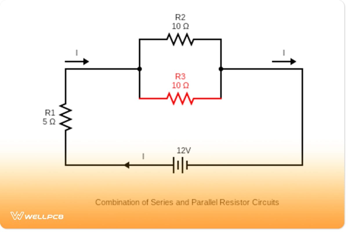
(Combination of series and parallel resistor circuit)
The equivalent resistance of a combination of resistors depends on their values and how connections are made. Hence, the total resistance in various series and parallel resistor circuits is found using Ohm’s Law.
First, R_total = Req(Series) + Req(Parallel)
Then, Req parallel= Req₂₃=(1/R2+ 1/R3)⁻¹
=(1/10Ω+ 1/10Ω)⁻¹ = 5Ω
Next, resistors 2 and 3, which are in parallel, are now in series with R1.
So, R-total=Req(series) +Req(Parallel)
Rt= 5 Ω+ 5Ω= 10Ω.
Combining resistors in series and parallel helps control currents while limiting potential drop across an electrical load.
Resistor Circuit Diagrams–Example application
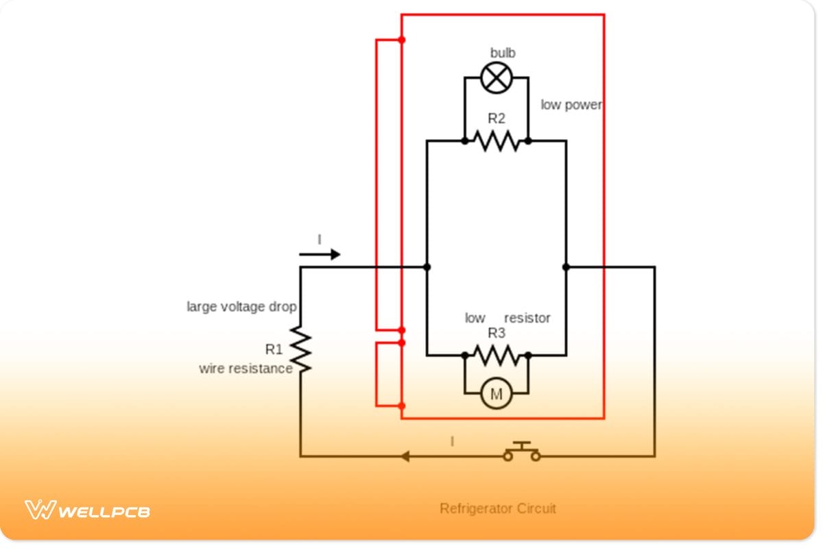
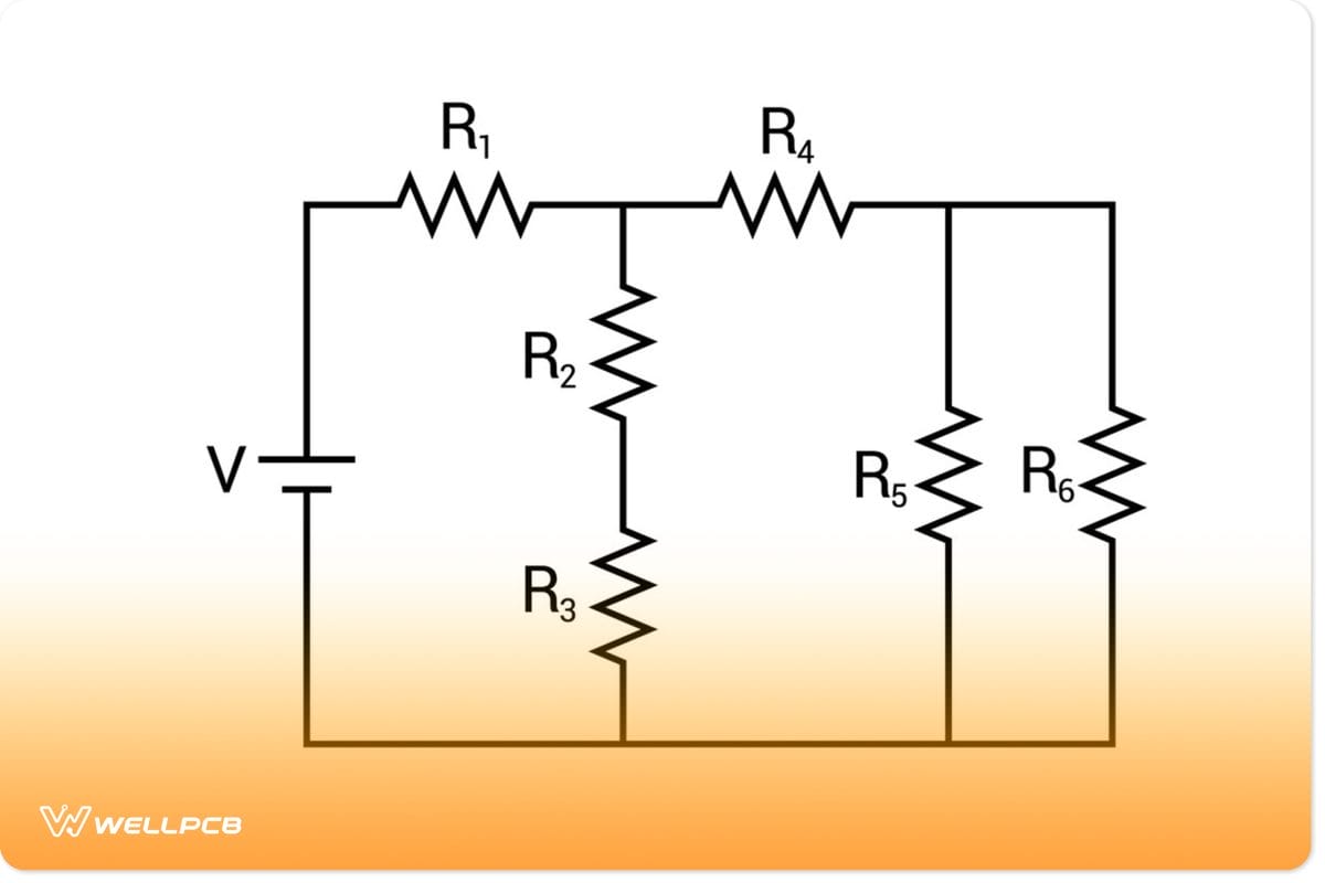
(Refrigerator circuit diagram)
In refrigerator circuits, a combination of resistor circuits is present. In the above diagram, when the fridge door opens, the bulb dims. It is because the motor of the fridge draws large current amounts. As a result, the bulb receives low power and hence darkens as R1 in the circuit experiences huge voltage drops. Resistor combinations help limit the maximum amount of current that passes through the circuit. At the same time, they provide specific potential reductions across electrical loads.
Summary
In conclusion, we have covered the three most common types of resistor circuit diagrams. We hope that now you have a better understanding of the different connection types and how they work.
Now, you can design your resistor circuits! If you have any further questions about how to do this, please get in touch with us.


