Nowadays, microelectronic components are vital in circuits. Most are improved versions of the basic ones. Examples include resistors, capacitors, inductors, and transistors. The silicon-controlled rectifier (SCR) is the most widely used semiconductor device.
In no small way, the IC‘s popularity is down to its vast scope of application. Some of which include power rectification, regulation, and inversion, to mention a few. The BT151 SCR is no exception. Here, we provide all about the SCR bt151, the pin configuration, and applications.
Contents
1. What is SCR BT151?
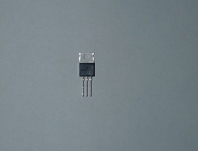
The SCR BT151, also referred to as a thyristor, is a particular semiconductor device. The silicon-controlled rectifier mainly consists of four different P-type and N-type materials enveloped in plastic. Conventionally, its primary purpose is to drive a high thermal cycling performance and block high bidirectional voltage.
Being a unidirectional device, it only allows current flow in one direction. And this becomes possible when there is triggering or biasing at the SCR gate terminal.
In other words, these transistor signal-controlled rectifiers behave like diodes. They stay conducting current until the anode-cathode current falls below a specific value. This value is the holding current.
The BT151, however, is a TO-220 package of SCR. In addition, it comes with a 12A medium power feature. As a result, it lets you alternate standard DC loads or power AC. Also, it gives room for managing DC signals on high levels.
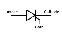
(The circuit symbol of the thyristor represents an SCR).
Source: Wikimedia
2. Pin Configuration for SCR BT151
Below is a description of the SCR BT151 pins and each terminal represents.
| Pin Number | Name Of Pin | Description |
| 1 | Cathode | This terminal is the outlet for the current supply. |
| 2 | Anode | Meanwhile, this pin lets current into the SCR. |
| 3 | Gate | It functions as a control mechanism for conduction between the cathode and anode. |
| 4 | Tab | On this end, the Tab goes to the anode terminal in an electrical connection. |
3. Features and Specifications of SCR BT151
Below are the features and specifications of the SCR BT151.
Features
- Its similar behavior to a thyristor is the first distinctive feature.
- The SCR BT151 has a high surge current capacity.
- Also, it has a high level of performance in thermal cycling.
- Unlike others, the rectifier device has high reliability.
- In addition, it possesses a high blocking voltage.
- Its blocking voltage is bidirectional, as well.
- The SCR BT151 comes in TO-22AB packages as well.
Specifications
- The surge current rating is at 132A.
- When biasing the SCR, the max for the gate trigger current is 15mA.
- Also, the maximum rating for holding current is at 20mA.
- The repetitive peak off current is 0.5mA.
- For the repetitive max reverse voltage, its rating is 500V.
- Likewise, the repetitive max forward voltage is also 500V.
- The on-state voltage is 1.75V, at maximum.
- The gate trigger voltage has an upper limit of 1.5V.

4. BT151 Equivalent SCR
Some electronic components function as equivalents to the BT151 SCR. They include:
- BT152.
- TYN208.
- 2N6508.
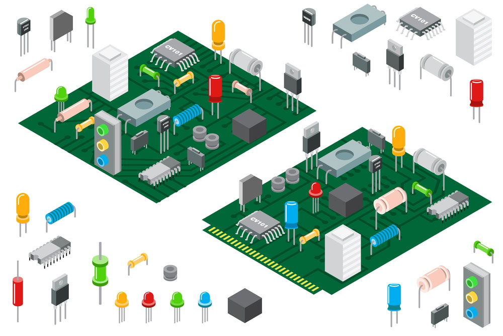
(The different types of thyristors arranged on a circuit board)
5. Circuit application of SCR BT151
In most cases, DC and AC loads use the SCR for control. That is in the regulation of current and voltage in devices. Furthermore, it is beneficial to line voltages with very high winds too.
Below, we demonstrate an ideal circuit application of SCR. We connect a DC motor load to a 12V DC supply using our BT151 SCR. However, the circuit only begins to function when the SCR conducts.
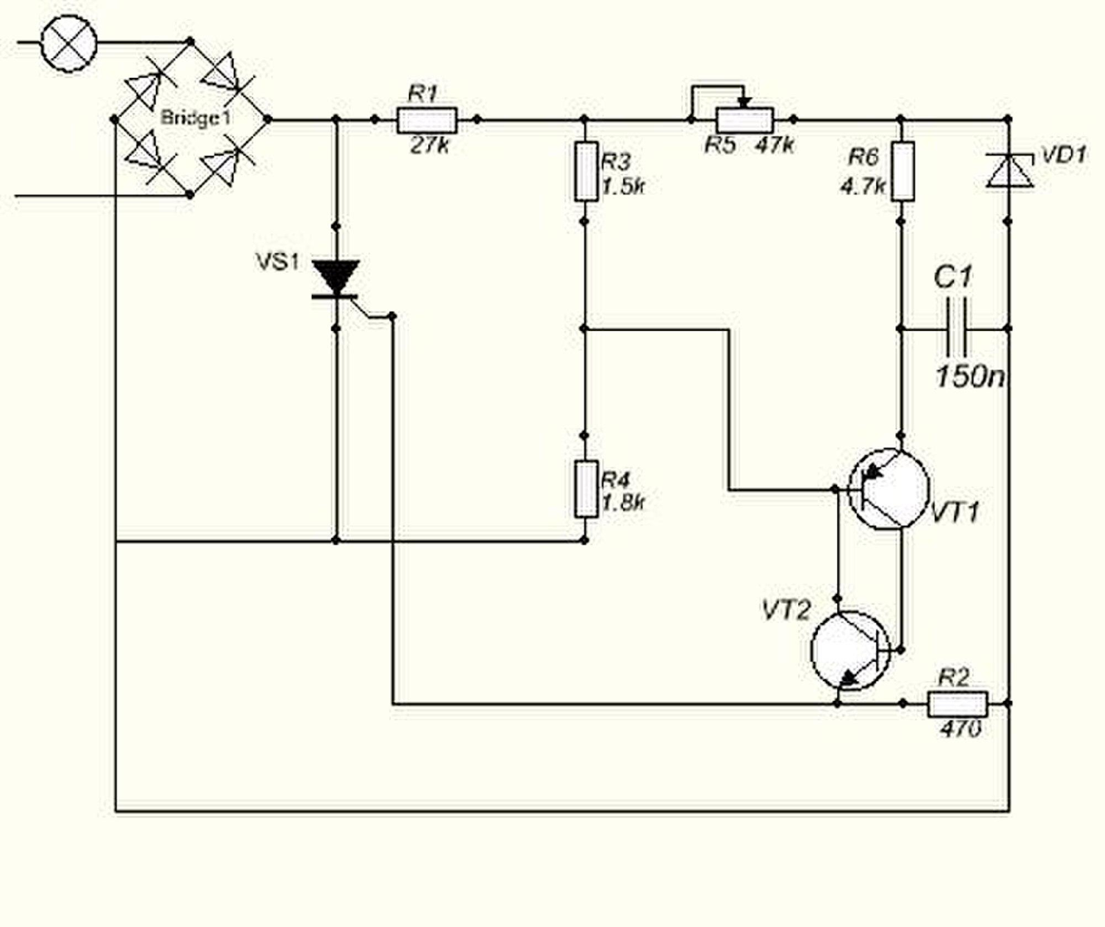
(A circuit diagram of an SCR operating as a power regulator).
Source: Wikimedia
How to Test an SCR?
A simple and efficient testing method for SCRs is to use a multimeter. By doing so, you verify the diode activity between the cathode and gate terminals of the SCR. To do this, you need the following steps:
- First, set the multimeter appropriately. You position the selector switch to the point of high resistance.
- Then connect the anode of the SCR to the +ve terminal of the multimeter.
- While the cathode of the SCR connects to the -ve terminal of the multimeter, these connections cause an open circuit display.
- Next, we reverse the connections made on the multimeter device to show the same results.
- Afterward, connect the anode and gate terminals of the SCR to the +ve end of the multimeter.
- On the other end, the cathode goes to the -ve terminal of the multimeter.
- As a result, the multimeter reading shows a reduced resistance because of the presence of a silicon-controlled rectifier.
- Finally, disconnect the gate of the SCR from the anode and cathode of the multimeter. The resulting display on the multimeter will read less resistance, thereby showing a latching condition. It indicates that the holding current for the SCR draws its power supply from the multimeter battery.
6. Application of the SCR Bt151
On the whole, SCR BT151 is of versatile importance in both domestic and industrial uses such as:
- For domestic lighting, heating, and static switching.
- For circuit protection and ignition alike.
- Additionally, it protects Inrush and Crowbar.
- BT151 SCR functions as a voltage regulator.
- It serves as a motor control mechanism.
- Capacitive Discharge Ignition (CDI).
- Generally used in circuits that require bidirectional blocking voltage capability.
(Switches like this use the SCR Bt151)
Conclusion
In summary, the BT151 is among a series of silicon-controlled rectifiers. These rectifiers function similarly to transistors, albeit with a latching ability. Thus, we term it a controlled rectifier.
Now that you know about the BT151 SCR and its operation, go ahead and build a project. Contact us if you have any questions; our experts are happy to help.


