Knowledge of electronic components and household technology can give you the power to troubleshoot things yourself. To better understand your home, try to learn about SPDT switch wiring. From there, you can discover how to wire your lights and fans correctly.
Contents
What Are SPDT Switches?
A single pole double throw switch, or SPDT, has one input and two outputs. Unlike other switches, you can control two circuits with one input on SPDT switches. And they do this through a two-mode capacity that lets you manage different circuits.
You can connect your SPDT wiring to flow in two different ways: manually or by employing an electromagnetic coil.
Different Types of Switches
When you’re wiring your home, you’ll most likely encounter the four basic types of switches. These include:
- Single pole, single throw, or SPST switch
- SPDT, as previously explained
- Double pole, single throw, or DPST switch
- Double pole, double throw, or DPDT switch
Different Types of Switches
How Do SPDT Switches Work?
An SPDT switch has a 3-pin toggle switch connection. The first terminal acts as the point of reference (common node) for the rest of the circuit. The other two terminals can connect and disconnect to this one by flipping the switch.
The two common configurations for SPDT toggle switch wiring are “on-off-on” and “on-on.” In both of these modes, only one load can receive energy at a time.
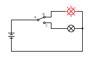
SPDT Switch Working
Let’s consider this schematic as having an “on-off-on” configuration. Terminal A has closed the circuit to terminal B, activating the component in series with this node. If A were to lie in between B and C, no components would turn on. Lastly, flipping the switch to connect terminals A and C would close the bottom circuit and activate the second component.
For the “on-on” mode, you would always have one component energized as long as the circuit has a power source. Terminal A would either connect to B or C but never lie in the center.

SPDT Applications
- ABB/Siemens VFDs
- Control Circuit
Control Circuit
- PLC output switches
- Selector switches, such as a single common configuration
Steps for Wiring an SPDT Switch
Many homes have one lightbulb controlled by two SPDT switches. These let you turn on a light at the bottom of the stairs and turn it off once you reach the top. If you encounter an issue with one of these switches, you will need to learn the basics of SPDT switch wiring to preserve your light source.

Light Bulb
Start by turning off the electricity at the distribution board or fuse box. Ensure you have a hot, neutral, and grounding wire for each switch. The hot wire connects to the down (or default) switch, and the neutral one attaches to a cable. This cable connects the switches to the light. Also, the grounding wire ties to the grounding screw in each switch box.
Here are two methods to wire SPDT switches.
Standard 3-Way Switch Wiring (3 Wire Control)
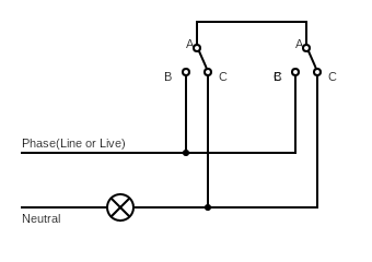
When you’re wiring a standard 3-way switch, you use a three-wire control. In this setup, the common nodes of both switches connect.
For simplicity, we will call the common terminal “A,” the left terminal “B,” and the right terminal “C.” Terminal B on both switches attach to the AC power supply line via a hot wire.
The two C terminals connect to one end of the lightbulb. Additionally, the other lightbulb terminal ties to the neutral wire on the AC power supply.
By toggling either switch, you can turn the light on or off. If both switches are in the same position, both common nodes are connected to either the B or C terminals. By flipping either one up, you can turn the light on because you change the closed circuit from A-C to A-B.
3 Wire Control
To reiterate, here are the two cases where the light will stay on:
| Switch 1 A (connected to) | Switch 2 A (connected to) |
| B | C |
| C | B |
The two instances where the light turns off include:
| Switch 1 A (connected to) | Switch 2 A (connected to) |
| B | B |
| C | C |
Most electricians use this technique since the neutral wires and line both come from the same breaker. However, this method uses more wiring.
2 Wire Control
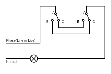
Some older houses and industrial buildings use the two-wire control method for SPDT toggle switch wiring. Keep in mind that few electricians will recommend this technique for modern homes as it does have several drawbacks.
Instead of both A terminals being connected, the B and C terminals of each switch unite. The common node of the first switch attaches to the AC power supply line with a hot wire. For the second switch, terminal A connects to one end of the lightbulb. And the second lightbulb node connects to the AC power supply’s neutral wire.
2 Wire Control
Similar to the first wiring method, the default state is off. Toggling either switch will turn on the light, and flipping them again will turn it off.
Despite this technique preserving cable, electricians do not recommend it because the hot and neutral wires can come from different breakers. Furthermore, these wires in proximity may interfere with each other’s electromagnetic (EM) radiation. And they can create an induction loop that hinders the radio frequency (RF) or EM signals.
Summary
It’s understandable that wiring an SPDT switch seems complicated, but the foundation of the knowledge relates to completing circuits. If you understand how wires connect within the electrical boxes, you’ll most likely correctly wire SPDT switches in your home.
Having information about electrical issues, including free energy, gives you a step up when it comes to wiring problems around the house. Once you master SPDT wiring, you’ll feel more confident tackling other electrical tasks.