
Contents
What is a Speaker Crossover?
It’s normal to hear sound frequencies from 20 to 20000 Hz.
However, it’s almost impossible to find a speaker that can generate frequencies throughout this frequency range.
So, you may assume that the best solution is to use many speakers.
Unfortunately, all speakers aren’t the same. Speakers have a specific build to produce a particular frequency response.
Hence, damage may occur if you make your speaker driver produce a frequency lower or higher than its range.
What if you use two or more speakers with similar frequencies and input sensitivity? In this case, the result will be louder frequencies.
Thus, it would help if you had a circuit that effectively handled the frequency problem. And the ideal circuit is the crossover.
With this, you can generate a specific set of woofer output frequencies.
However, it’s vital to note that the crossover may not block out all the frequencies above the crossover point.
Instead, the device filters the audio band frequencies—and it does this in huge amounts as the band of frequencies exceeds the crossover point.
Categories of the Speaker Crossover
How fast can the crossover filter frequency be? It all depends on the crossover’s acoustic performance order. Here are examples of how varying orders filter frequencies with different speeds:
- 1st order – 6dB / octave slope
- 2nd order – 12dB / octave slope
- 3rd order – 18dB / octave slope
- 4th order – 24dB / octave slope
- 5th order – 30dB / octave slope
Also, you can measure the frequencies with a logarithmic scale. And the octave refers to the frequency’s halving or doubling.
Further, the attenuation slope is another aspect you should consider. And it’s the rate at which signals reduce past the crossover frequency.
So, the crossover will have steeper slopes when you have a higher decibel.
What Makes Up the Crossover?
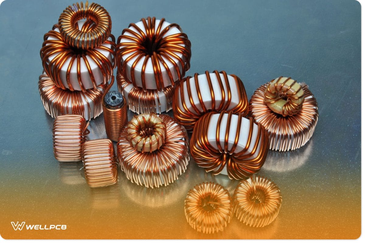
Capacitors and inductors are the primary components of crossovers. And when the frequency rises, the inductor becomes more reactive.
As a result, the AC resistance will increase, and the sound pressure on the driver will keep reducing.
The capacitors aren’t left out as well.
They go in the opposite direction. When frequency decreases, capacitors become more reactive, and hence, the AC resistance will increase.
That said, here are three ways you can crossover frequencies:
BandPass Filter
The bandpass filter works by combining the low-pass and high-pass filters.
It permits a range of frequencies, typically below and above two specific crossover frequencies.
That is, there will be one low pass and one high pass. Thus, both frequencies go through to a group of speakers.
High-Pass Filter
This filter helps you to permit frequencies higher than the chosen cut-off frequency to go through a group of speakers.
Low-Pass Filter
This filter permits frequencies less than the chosen cut-off frequency. The frequencies move to the group of speakers.
Types of Crossovers
We have two major types of crossovers. And the difference between both crossovers is what they use to divide the frequencies.
Passive Crossover
The passive crossover combines inductors, resistors, and capacitors to get the preferred crossover point for a group of speakers.
Interestingly, this crossover is affordable. It provides an impressive switch between tweeter and midrange. However, the drawback is that the filters are usually large. Hence, you can only use it for smaller speakers.
That said, the subwoofers need heavy and huge inductors. It can handle all the power and permit only low frequencies through a small filter.
Further, you may find passive crossovers with high-end coaxial speakers and components.
Electronic Crossover
The electronic crossover is more expensive than the passive crossover. This is no surprise, considering that the former divides frequency with a microprocessor or DSP chip.
This crossover is a flexible system. It allows you to pick your preferred crossover types and adjust them accordingly.
Also, you get an instant change when you adjust the crossover frequencies.
Further, if you want a crossover that will allow you to fine-tune a speaker system with channels of amplification per speaker—opt for the one with advanced DSPs.
In addition, most basic electronic crossovers provide only low pass output band and high pass capabilities.
Working Principle of the Speaker Crossover Circuit
The circuit system works with the filtering system. So, when input audio signals go into the circuit, the capacitor and inductor filter them.
As mentioned earlier, the capacitor usually has a low reactance at high frequencies and a high reactance at low frequencies.
Consequently, the capacitor won’t permit low-frequency signals. But it will allow the high-frequency pass.
So, that’s how the capacitor moves the high-frequency surround sound to the tweeter.
That said, you can calculate the capacitance reactance with the formula below:
- Xc = 1/ (2πfC)
Where:
- C – capacitance of the capacitor
- F – is the audio signal’s frequency
On the other hand, the inductor has a low reactance at low frequencies and a high reactance at high frequencies, so it doesn’t permit high-frequency signals.
But it allows the low-frequency signals. That said, this is how the inductor channels low-frequency signals to the woofer.
With this network, you have a speaker crossover network. The woofers are responsible for playing low-frequency sounds perfectly.
Also, the tweezers produce high-frequency sounds effectively.
Hence, connecting these two speakers in a system over a single general speaker will give you a better system.
Also, you can calculate the inductor reactance with the formula below:
- Xc = 2πfL
Where:
- f – audio signal’s frequency
- L – is the inductor’s inductance
How Do You Build a Speaker Crossover Network Circuit?
Before you start building the amplifier power speaker crossover network circuit, it’s vital to get the following components:
- 2.55mH inductor
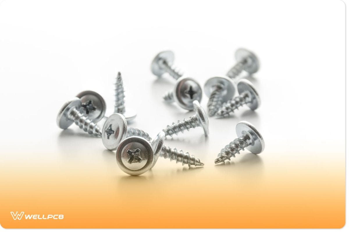
- Screws (10)
- Glue
- Woofer
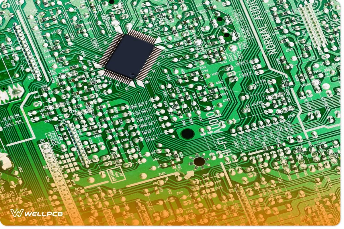
- 1/4” thick acrylic or regular circuit board (1)
- Banana Jacks (2)
- 1/4” plastic tubing (4)
- Hardboard
- Rig
- 39uF electrolytic capacitor
- Tweeter
- 3/4” dowel
- Nuts (2)
With that in mind, it’s crucial to note that you can use inductors and capacitors with closer values—if you can’t find these exact ones.
Speaker Crossover Wiring Diagram–Steps
Step 1
First, you have to reference the speaker crossover wiring diagram to understand how to connect the components. And you have to do this because the filters tend to release signals out of phase at 1800. That said, you can start by doing reverse wiring for the woofer.
Step 2
So, if your woofer is less sensitive than your tweezer, add an L-pad. The L-pad effectively reduces the difference in sensitivity. Next, make a simple winding. You can do this with some hardboard and a dowel (3/4”).
Step 3
Then, place your full coil on a rig. Consequently, it will hold your inductor as it unspools. Fine-tune your coils. While you’re at it, remember that some of the factors will affect the inductance of your coil. Some examples are the diameter of the hole, tightness, and height of the wind. Also, you should have two small coils and two big ones.
Step 4
Get your circuit board. This component usually has holes in the middle. The holes are for tie straps—effective for firmly holding your capacitors and coils. So, when you finish the task, take note of the holes at the board’s edges—as they are the connection terminals.
Step 5
Fix your low-pass components firmly on your circuit board. Also, if you want a clean result that’s fast and easy to install, use banana jacks. You can fix the jacks behind to connect your speaker wire. Then, put two nuts on each jack and secure them with hot melt glue or super thick glue. That way, the nuts won’t come off.
Step 6
Arrange the 1/4” plastic tubings in the box before mounting the crossover board. Then, drive in the screws—one in each corner.
Step 7
You should see wires coming from the banana jacks on the right-hand side at this stage. And on the left side, you should have wires leading to the tweeter and woofer.
Wrapping Up
The speaker crossover wiring diagram is one of the steps to understanding how to connect the device properly.
Paying attention to the components you use to set up your crossover speaker is also crucial. It will greatly affect the quality of your final results.
What do you think about this audio crossover project?
Do you need help finding the best circuit boards for your project? Please feel free to contact us.


