Wire Ampacity Calculator–Content
The DC resistance of a conductor can be calculated using the following formula:
Where R = Resistance of the conductor
ρ = conductivity of conductor, measured in ohms (Ω)
l = length of the conductor
A = effective cross-sectional area of the conductor

The voltage drop in low voltage systems becomes more significant due to IR drop. This is because the standard voltage systems operate relatively at higher currents. If the wire size or diameter is too small, it creates more power losses around it that cause a temperature rise; conversely, a higher diameter wire causes an increase in cost.
The ampacity calculation, according to the Neher-Mcgrath, is:
- Wire Ampacity Calculator
- Where I = Ampacity in amperes
- Tc = conductor temperature
- Ta = Ambient temperature
- delTD = conductor temperature rise
- Rdc = conductor DC resistance
- Yc = conductor loss increment
- RCA = conductor thermal resistance
The voltage drop in a conductor with current flow becomes a significant value in pcb assembly and can be estimated by Ohm’s law:
- I = current in amperes, measured in Amperes
- V = voltage drop across the conductor ends
- R = resistance of the conductor
Longer cables have more dc-resistance, and high voltage drops across them, so the higher heat losses.
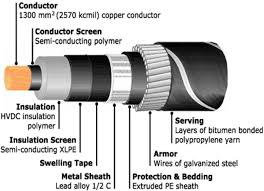
Fig 1: The structure of a conventional high voltage-current carrying cable
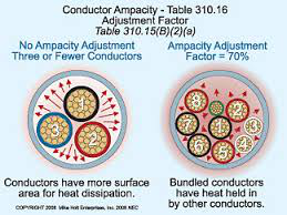
Fig 2: A comparison of two cables compensated for heat dissipation and without heat dissipation