
Contents
What Is A Start-Stop Circuit?

Fig 1: An Electrician Testing An Industrial Machine
A start-stop circuit is an electrical circuit that starts or stops electrical components, including motors or ladder logic networks.
They’re generally critical in machine control and control systems to start/stop a motor, a machine, or a process.
What Components Are Key In A Start Stop Circuit?
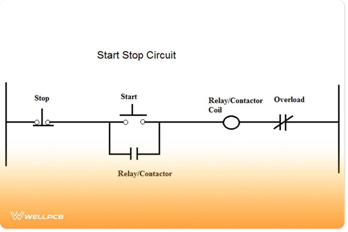
Fig 2: Schematic Representation of a 3-Wire Control Start-Stop Circuit
There are several compulsory components of any start-stop circuit. This section will take an in-depth look at the four elements.
Buttons/Contacts
Buttons or contacts in start-stop circuits are ideally the switches that turn on or off the course. Their principles of operation are to complete or break an electrical circuit manually or automatically.
Relay/Contactor
Relays and contactors are electromagnetic or electric switches that close or open circuits depending on a specific stimulus.
However, contractors are special relays, while relays are not contractors.
Also, contactors are applicable with higher current circuits, while relays are vital to switching smaller current drawing courses.
Contactors are Normally Open (NO) and will only close the circuit when its coils energize or close. A relay can be in a Normally Open (NO) state or a Normally Closed (NC) state.
Therefore, energizing the relay coils results in a NO circuit becoming an NC and an NC circuit becoming a NO.
Relays control larger circuits by using the amplification effect. You activate them by applying a fraction of the line voltage to its coils to control larger-voltage systems.
Motor
Motors provide the kinetic movement necessary to move conveyor belts, machinery, or pump water in start-stop circuits.
Motors vary greatly depending on the task under execution, the load capacity, or even the type of control.
Overload
Overload or overload relays are protective relays that open an electrical circuit if a thermal, power or electrical overload happens.
They’re typically closed (NO), meaning they’ll only be operational once they detect an overload.
Furthermore, the ratings and use of overload relays are variable. Hence, the a need to check your relay rating before installing one to protect your motors and other accessories.
The Electrical Supply Required For A Start Stop Circuit
The type and magnitude of power supply to a start-stop circuit are variable. The voltage level depends on your start-stop circuit configuration and the kind of control.
However, a common control voltage of 24V DC is preferable for most start-stop circuits. You can power control circuits to operate at lower voltages than the components they’re controlling.
In this way, an operator can use a 120V AC start button to control a 600V motor. And given that this is common in 3-wire control, the high-voltage switches must be away from the operator.
Control power can enter a circuit directly from the line, through a control transformer, or by a separate source.
The Working Principle Of A Start Stop Circuit
The working of a start-stop circuit relies on the relays, buttons, motors, and overload relays.
To better understand, the black lines will represent components without power, and the blue bars will represent components with passion.
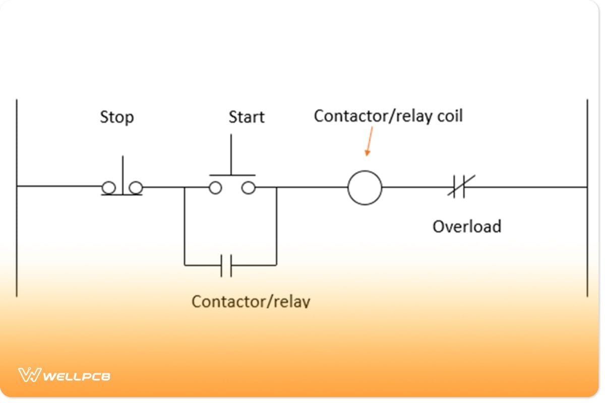
Fig 3: An Unpowered Start-Stop Circuit Schematic
As shown, the start-stop circuit is in its OFF state. The normally closed stop button is shut in such a state while the Normally Open start button is open.
In this state, the relay/contactor coil is unenergized, and the motor is isolated from the power supply.
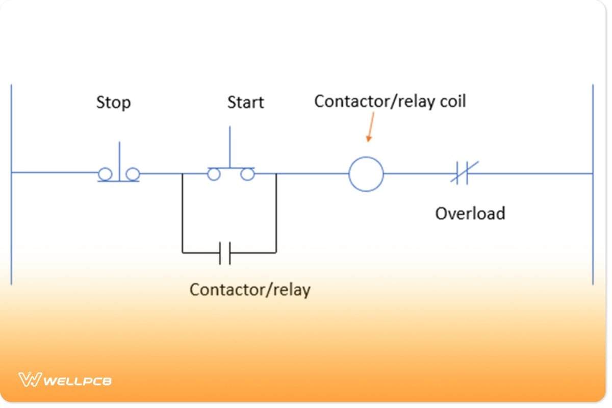
Fig 4: A Powered Start-Stop Circuit Schematic With Start Button Pressed
Pressing the start button allows the current through the circuit, which energizes the relay/ contactor coils and the motor. The motor coils energize, and the engine starts running.
Notice that the overload relay contact remains in close mode while the NO relay coil remains open.
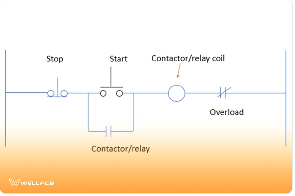
Fig 5: A Powered Start-Stop Circuit Schematic With Start Button Released
You press the start button briefly for start-stop circuits to allow power flow and then release it. The power will energize the relay or contactor coils. After removing the start button, the NO contactor/relay coils provide an alternate path for the current flow.
Therefore, the motor runs up until a point when there’s a power loss. You press the stop button, or the overload relay trips.
The circuit will then be in an OFF state until you press the start button once more.
Ways To Control The Wiring In A Start-Stop Circuit
2 Wire Control
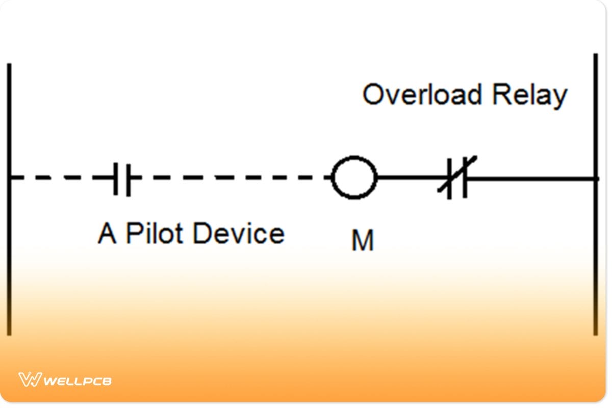
Fig 6: A 2-Wire Start-Stop Circuit Control
A 2-wire control for a start-stop circuit uses a starter coil in series with a contact pilot device. The most common contact pilot device in use includes a pressure or limit switch.
We use it when the circuit is to operate without external intervention. If there is power loss while the switches’ contacts are still in close mode, the relays pick up automatically.
Therefore, the circuit becomes complete once the power is back. In 2-wire control, only two wires connect the starter to the pilot device.
3 Wire Control
In a 3-wire circuit, you need three wires to connect the starter to the pilot device. It uses momentary switches to “start” or energize the starter coils.
Therefore, they require external stimuli such as the brief pressing of a start button to close the circuit. Connect an auxiliary starter circuit in parallel to the start button. Ensure the motor receives power once you release the start button.
In the case of a power loss, the circuit undergoes de-energization. Therefore, the start button has to be pressed briefly to close the course once more.
Conclusion
Electricity is equally as crucial as it is dangerous. Therefore, knowing how to construct safer and more manageable control circuits is essential.
Furthermore, the electrical world is ever-evolving as we incorporate more automation into our lives. Don’t be left behind.
We are more than willing to guide you on start-stop circuits to get the most out of your project.
Contact us today for more knowledge, materials, or guidance on start-stop circuits.


