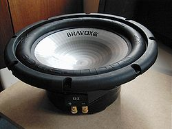
A subwoofer driver
Source; Wikipedia
Today, we will design a subwoofer/stereo amplifier circuit that produces low-frequency audio signals ranging from 20Hz to 200Hz. The sound output power is 100W, and it uses a 4-ohm speaker load for its operation.
- What are Subwoofer Amplifier Circuits?
Subwoofer amplifier circuits are loudspeakers that produce low-frequency audio signals. In other words, they ensure that the bass quality of your loudspeaker increases by amplifying the input audio signals. Similarly, they eliminate any harmonic distortion.
A passive subwoofer is an example of a subwoofer. It gets power from an external amplifier and has a speaker enclosure design.
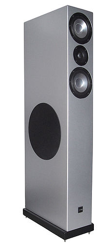
A loudspeaker
Source; Wikipedia
- Subwoofer Amplifier Circuit Principle
The principle of a subwoofer amplifier circuit involves amplifying the audio signals of low frequencies.
- First, the amplifier filters the audio input signal to eliminate high-frequency signals.
- Next, a voltage amplifier amplifies the low-frequency signals.
- Afterward, several configurations raise the low voltage signal to a needed level.
- Lastly, a transistor converts the amplified version of a low-frequency sound into power signals. Eventually, the power signals produce bass/ loud bangs and minimal noise.
Pro-Tip
- Position the subwoofer speaker in a corner for the best coupling to the room’s air volume and best efficiency.
- Additionally, enclosure variations can help reduce the amplifier power requirements and increase the efficiency of the subwoofer drive.
- When on a personal connection, ensure you use anti-virus to scan your device to reduce the chances of infected devices.
Contents
100-Watt Subwoofer Amplifier
Circuit diagram
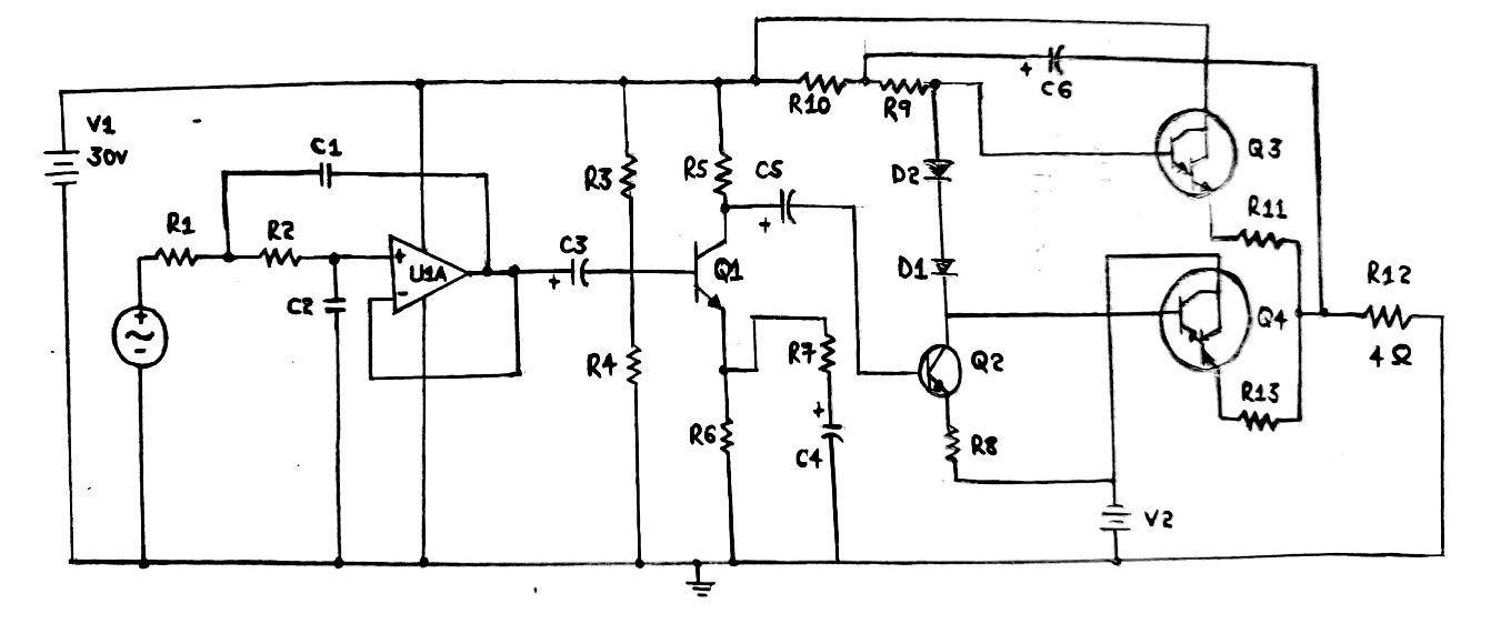
The Circuit diagram of a 100-watt subwoofer amplifier
Circuit Components
As per the diagram above, we can see that the components in making a 100 Watts stereo amplifier circuit include:
- Dual power supply – +/-30V
- Q1 – 2N222A
- Q2, Q3 – TIP41
- Q4 – TIP147, PNP
- R1, R2 – 6K
- R3 – 130K
- R5 – 15K
- R6 – 3.2K
- R7 – 300 ohms
- R8 – 30 ohms
- R9, R10 – 3K
- D1, D2 – 1N4007
- C3, C5, C6 – 10uF, electrolyte
- C4 – 1uF, electrolyte
- C1, C2 – 0.1uF, electrolyte
Depending on the components, we’ll have amplifier sub-circuit ideas that will also be handy during your amplifier project.
Audio Filter Design
For the first design, you’ll use an Operational amplifier LM7332 to construct a Sallen-Key low-pass filter.
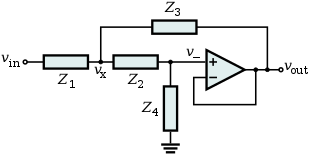
A Sallen-key filter topology
Source; Wikipedia
Let’s assume the cutoff frequency is 200 Hz and the quality factor is 0.707. Additionally, let’s have the number of poles equal to one and the C1 and C2 values equal to 0.1uF.
Therefore, to find a similar value of R1 and R2, we can use the formula below by substituting known values.
R1 = R2 = Q/(2*pi*fc*C2)
The resulting value for each resistor is 5.6K. However, for better accuracy, we’ll settle for 6K for R2 and R1.
We’ll not include the resistors at the non-inverting terminal for the adjustable low-pass filter because we want a closed-loop gain filter without a short at the output terminal.
Pre-Amplifier Design
In a pre-amplifier design, we’ll apply the class A operation of the 2N222A transistor.
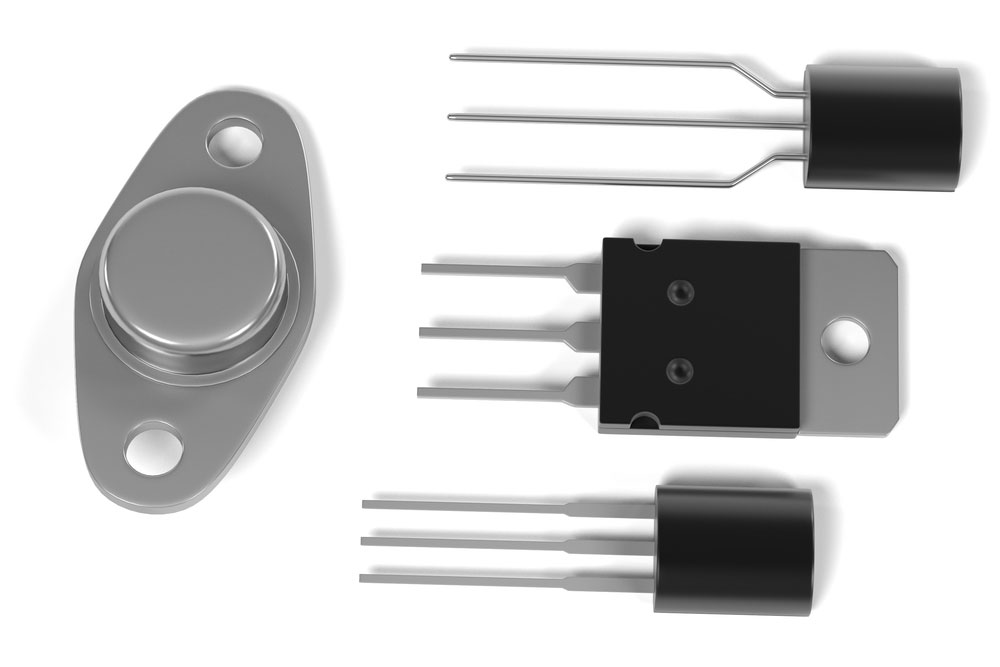
(transistors)
We’ll further need a supply voltage of 30V, a load resistor of 4 ohms, and an output power of 100W.
We can have a collector quiescent voltage of half the supply voltage (15V) and a collector quiescent current of 1mA.
Then, when calculating the load resistor value, it should equal 15K.
R5 = (Vcc/2Icq)
Base Current is, Ib = Icq/hfe
If we substitute the AC gain/ have value in the above formula, the base current should be 0.02 mA. Likewise, Ib or bias current is often ten times the base current. Therefore, it totals up to 0.2mA.
Also, the emitter voltage/Ve, roughly 12% of the power supply voltage, is at 3.6V. You can now get the Vb/voltage base by adding 0.7 to Ve, i.e., 4.3V.
The formula below helps in getting the values of R4 and R3;
R3 = (Vcc – Vb) Ibias and R4 = Vb/ Ibias
If we substitute the values, R4 will be 22K, whereas R3 will be 130K.
The emitter resistor’s resistance (Ve/Ie) is at 3.6K, a value shared by R7 and R6.
R7 acts as the feedback resistor, decreasing C4’s decoupling effect. To get the value of R7 only, we calculate the values of gain and R5, which are 300 ohms. Therefore, the R6 value becomes 3.2K.
Finally, the value of C4 is 1uF since the emitter resistance should be more than the capacitive reactance of C4.
Power Amplifier Design
The power amplifier AB has a class AB mode operation that uses Darlington transistors, namely TIP147 and TIP142. Hence, the biasing diodes you select should have similar thermal properties to the transistors, i.e., 1N4007.
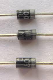
A 1N4007 diode
Source; Wikimedia
3K for the resistor R9 is suitable because the low-bias current requires a high-bias resistor value. Moreover, the power amplifier gets a high-impedance input from the driver stage. Thus, we’ll use the TIP41 power transistor in a class A mode operation.
The value of R8 equals both the emitter current (0.5A) and emitter voltage (1/2Vcc—0.7) values. The final value becomes 28.6 ohms, but in this case, go for a 30 ohms resistor.
Bootstrap resistor R10 should offer high impedance to transistors TIP147 and TIP142. Therefore, 3K is recommendable.
Subwoofer Amplifier Circuit Operation
The step-wise explanation gives the basics of a subwoofer amplifier circuit operation.
- The Sallen-Key low pass filter from the above designs filters out the audio signal. Only frequencies equal to and below 200 Hz pass the filter as the remaining undergoes filtration.
- The input of Q1 through the coupling transistor and C3 receives the low-frequency signal. Since Q1 operates in class A mode, it will improve the version of the audio input signal at its output.
- Then, Q2 converts the amplified signal into a high-impedance signal before passing it to a class AB power amplifier.
- TIP147 and TIP142 give a complete cycle of the output signal. One transistor conducts for a negative half cycle, while the other is for a positive half cycle.
- Furthermore, R13 and R11 reduce the differences amid the matching transistors.
- The diodes keep minimal cross-over distortion.
- Ultimately, the high-power output signal operates a subwoofer/loudspeaker with a low impedance, approximately 4 ohms.
Applications of Subwoofer Amplifier Circuit
A couple of applications of a subwoofer amplifier circuit include;
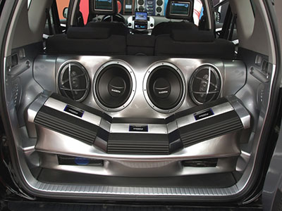
- For sound applications you’ll mostly find them in places like concerts, electronic dance music, or reinforcement system applications. Even your car, some select theaters, or home theater systems have one of the circuits.

(a home theater system)
- Long-range transmission in case you want to draw the power for high-range antennas.
- You can use them as power amplifiers for the lowest frequency signals.

Limitations of Subwoofer Amplifier Circuit
They comprise;
- First of all, our circuit illustration is theoretical, and the output sometimes has distortion, like in acoustic music genres.
- The biasing may also be disrupted since the filter circuit sometimes upsurges the audio signal’s DC level.
- Other times, the circuit can’t remove noise disturbances like conventional loudspeakers.
- Lastly, the circuit’s efficiency is reduced because of the linear devices that cause power dissipation.
Conclusion
A subwoofer amplifier circuit is the surest way to create a low-frequency sound. Our post highlights the steps to achieve better sound application quality.
However, if you still have questions or need clarification, contact us, and we’ll reply.


