It’s not enough to build high-powered electronic circuit boards or machines that use engines. Why? Because such projects won’t be complete if you can’t give the full details. Or even the specifications of the machine’s engine.
Yes, we’re talking about the rotational speed of the engine. And, to do this, you’ll need a tachometer. That’s why Tachometers are essential when it comes to automotive and aviation applications. So, in this article, we will learn everything about a tachometer Circuit and how to make a simple tachometer circuit. Are you ready? Let’s begin!
Contents
What is a Tachometer?
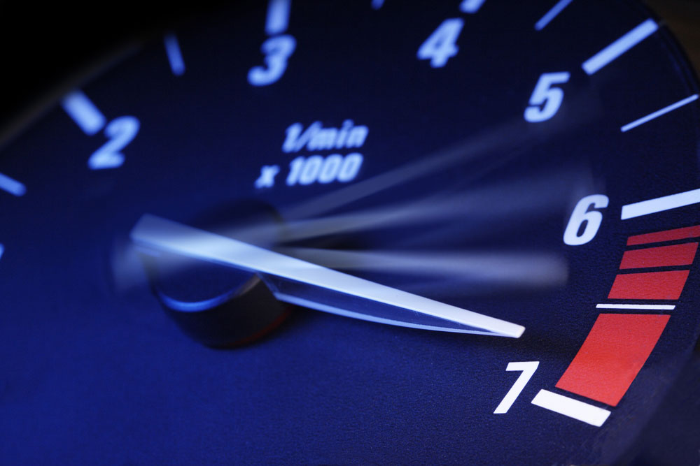
Analog Tachometer Meter
The most important thing to measure is the revolutions per minute (RPM) for engines. Seemingly, it’s one of the features that shows how fast an engine can go.
Plus, it prevents you from damaging your engines. That’s why it’s necessary to have tachometers when working with engines or motors,
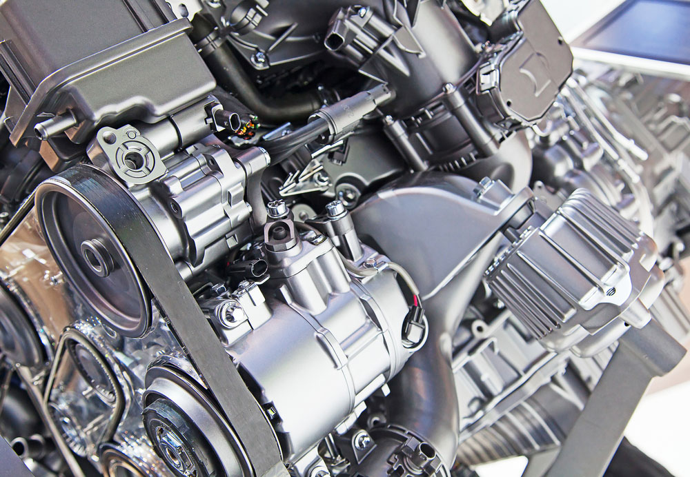
Engine
But, what exactly is a tachometer?
Tachometers are sensor devices that measure the RPM of objects that can rotate like engine shafts. Usually, these types of sensors work for only electrical or mechanical instruments.
However, there are cases where advanced tachometers measure the time period and speed range of other things. So, an example of such advanced tachometers is the haematachometer. This tool measures the speed of blood flow.
Types of Tachometers
There are four main types of tachometers with different specifications.
And they include:
Analog Tachometers
Analog tachometer circuits use a dial-type interface and a needle to indicate the current readings of the engine speed.
Again, these tachometers can’t measure extra details like deviation and average.
So, the analog tachometer uses an external frequency to voltage converter to measure the RPM. It also displays the converted voltage via an analog voltmeter. Plus, these tachometers don’t have the technology for the storage of readings.
Digital Tachometer
Digital Tachometer RPM Display
Unlike analog tachometers, digital tachometers have the memory to store readings. They also utilize digital displays like LCD or LED displays to indicate current readings.
You can use these tachometers for high precision measurement applications and statistical operations. Additionally, you can monitor time-based quantities with this tachometer.
Furthermore, you’re more likely to find digital tachometers in today’s technology. Plus, they show their measurements in numerical readings—not dials and needles.
Time and Frequency Tachometers
The time and frequency tachometers both employ different working principles. First, the time measuring tachometer computes the maximum speed. So, it measures by calculating the time intervals between an inbound train of pulses.
On the other hand, frequency measuring tachometers measure speed by calculating the frequency of inbound pulses.
Additionally, time tachometers work best for low-speed measurements, while frequency tachometers can run high-speed measurements.
Contact and Non-contact Tachometers
Both the contact and non-contact tachometers work as data acquisition methods. On the one hand, the contact makes use of an optical encoder or magnetic sensor. So, it uses them to measure speed when it contacts the rotating shaft.
On the other hand, non-contact utilizes laser or optical disks and doesn’t require physical contact to measure speed.

Applications
- Laser applications
- Traffic volume and expected speed estimation
- Different prime movers and machinery applications
- Automobile and aviation applications (e.g. measuring an air engine speed)
- Analog audio recording applications
- Medical applications
How to Make a Tachometer
So we’ll learn how to make a simple tachometer circuit using Arduino.
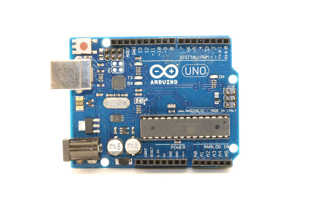
Arduino Board
Schematics
This simple tachometer circuit isn’t expensive, and it uses the concept of infrared waves. We can’t see these waves, but their wavelength has a longer reach light we can see.
For this circuit, we’ll use an IR sensor as a major component. This IR sensor has two LED bulbs which act as an emitter and a receiver. Thus, the LED which emits IR rays is the IR transmitter while the other (receiver) is the IR photodiodes.
Additionally, these bulbs look like normal LEDs and photodiodes. But, they only emit and receive infrared rays.
So, when you turn on this IR sensor, the IR transmitter starts releasing IR rays to the object you want to measure.
Here’s where things get interesting.
When the object reflects the rays, the IR photodiodes will receive them and generate voltage. Now, the generated voltage depends on the intensity of the reflected rays. In other words, the higher the intensity, the higher the output voltage.
Finally, it sends the voltage as output through the Arduino output pin via the LM358 IC.
Necessary Tools
- Arduino board (1)
- IR sensor (1)
- 16X2 LCD module (1)
- Some connecting Wires
- Solder
- Soldering Iron
Construction and Testing
Here are the steps you need to follow:
Step 1: Gather your Components
Assemble all your components and make sure everything works properly before construction.
Step 2: Connect your Components
Connect the VCC and GND of the LCD and IR sensor to the GND and 5V pins of the Arduino.
Next, connect an IR sensor’s OUT to pin together with the digital pin 2 of the Arduino board.
Finally, connect the SCL and SDA pins of the LCD to the Arduino’s A5 and A4.
Step 3: Coding
Once you’ve connected every component, the next step is to code your Arduino UNO. Here is the code you should use:

//DIY Tachometer to Measure Accurate RPM using Arduino
//DIY Tachometer to Measure Accurate RPM using Arduino
//This code is published by https://www.circuitschools.com
//Attribution required to republish.
#include <LiquidCrystal_I2C.h>
// Create the lcd object address 0x27(get it from i2cscanner) and 16 columns x 2 rows
LiquidCrystal_I2C lcd (0x27, 16,2); //
float value=0;
float rev=0;
int rpm; oldtime=0; newtime;
void isr() //interrupt service routine
{
rev++;
}
void setup()
{
lcd.init (); //initialize LCD
// Turn on the backlight on the LCD.
lcd. backlight ();
attachInterrupt(digitalPinToInterrupt(2),isr,RISING); //attaching the interrupt
}
void loop()
{
delay(1000);
detachInterrupt(0); //detaches the interrupt
newtime=millis()-oldtime; //finds the time
int wings= 3; // no of wings of rotating object, for disc object use 1 with white tape on
one side
int RPMnew = rev/wings; //here we used fan which has 3 wings
rpm=(RPMnew/newtime)*60000; //calculates rpm
old time=millis(); //saves the current time
rev=0;
lcd.clear();
lcd.setCursor(0,0);
lcd.print(“___TACHOMETER___”);
lcd.setCursor(0,1);
lcd.print( rpm);
attachInterrupt(digitalPinToInterrupt(2),isr,RISING);
}
Step 4: Testing
Once you complete all the above steps, try out your completed tachometer project. So, the device should detect any object as an obstacle when emitting IR rays and properly receive the rays when reflected.
Thus, when the object rotates, the device should count how many times the object was an obstruction and create the necessary voltage according to the reflection intensity.
Note: This tachometer is light-sensitive, so you might not get accurate results in well-lit environments.
Motor
Rounding Up
There’s nothing complex about how a tachometer works. It works using the principle of relative motion between the shaft and the magnetic field of the device. Additionally, tachometers have motors that generate voltage depending on the velocity of the motor shaft. In other words, it counts the number of rotations the motor shaft makes per minute when in motion.
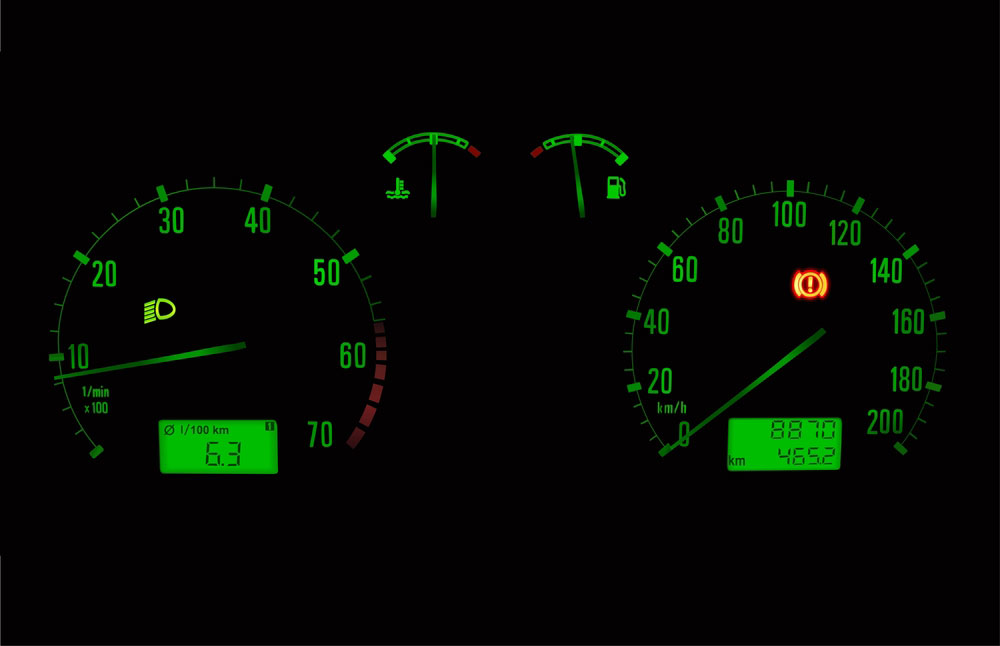
Sometimes, people confuse the tachometer with the speedometer. Although they both measure speed, these two devices perform entirely different functions. While the tachometer meter measures the speed of engines, speedometers show the speed of vehicles.
Speedometer
That rounds up this article. If you have more questions about tachometers, feel free to reach out to us, and we’ll be happy to assist.


