Contents
- 1 When do we Need to Test a MOSFET?
- 2 Components Required to Test a MOSFET
- 3 How to Test a MOSFET?
- 3.1 Method 1: Using a measuring meter
- 3.2 Method 2: Testing a MOSFET–Using electronic components
- 3.3 Method 3:Testing a MOSFET–Using a measuring meter
- 3.4 Testing a MOSFET–Diode Test
- 3.5 Testing a MOSFET–Resistance Test
- 3.6 Testing a MOSFET–By using an ohmmeter and multimeter in diode mode
- 3.7 Method 2:Testing a MOSFET–Using electronic components.
- 4 Conclusion
When do we Need to Test a MOSFET?

Figure 1: Parts of a MOSFET
Testing a MOSFET before connecting it to a circuit is an essential thing for protecting the other components. A MOSFET comprises three main parts.
They include the drain, source, and gate. When one uses a faulty MOSFET, a shorting of the drain to the gate happens.
It is harmful to the circuit.
The resultant effect of this shorting can be drain voltage feedback, which affects the gate terminal as well.
After reaching this terminal, the voltage further passes to the driver circuit via the gate resistor. This transmission can result in further damage to the driver circuit.
Preventing such damage is why testing a MOSFET is imperative before using it to avoid damaging the entire circuit.
Components Required to Test a MOSFET
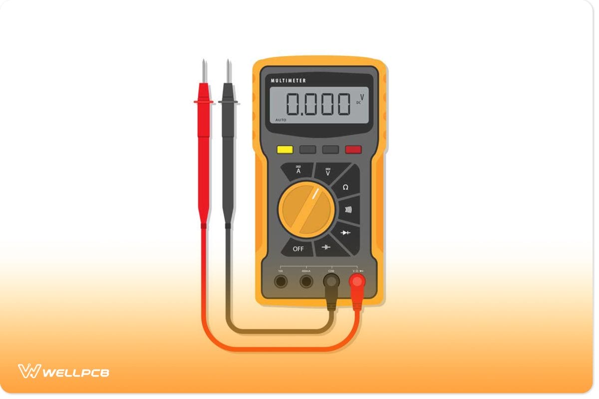
Figure 2: A Digital Multimeter
When testing a MOSFET, you first need to assemble the necessary components. The most commonly used MOSFET is the N-Channel MOSFET, also known as NMOS. The testing of the N-Channel MOSFET requires the following elements:
- A 5V DC power source
- One measuring meter- This can be either an Ohmmeter or a multimeter with a resistance range.
- One multimeter with a diode mode
- A Q1 MOSFET
- One 100E Resistor
- One 10K Resistor
- One 220E Resistor
- One general-purpose LED
- One Pushbutton Switch
How to Test a MOSFET?
You can use two main techniques to test the effectiveness of a MOSFET. These include using a measuring meter and using electronic components.
Method 1: Using a measuring meter
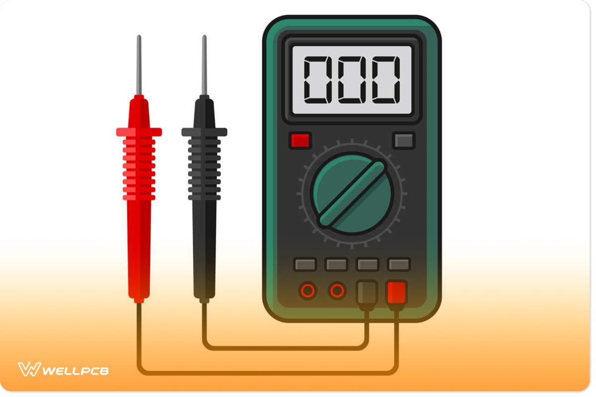
Figure 3: A Digital Multimeter
This technique involves checking if the MOSFET is working by testing with an Ohmmeter or multimeter. For this option, you can choose to use any of the following three main ways.
- Conduct a diode test. This operation will require a multimeter with diode mode.
- Resistance test.
- You can also opt to use a multimeter and ohmmeter in diode mode
Method 2: Testing a MOSFET–Using electronic components
This method requires the assembly of a test circuit to test whether the MOSFET is functioning appropriately.

Figure 4: An electric circuit board
Method 3:Testing a MOSFET–Using a measuring meter
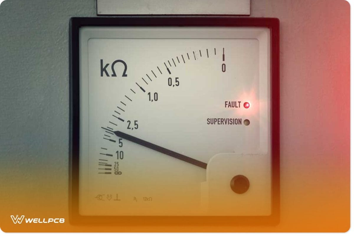
Figure 5: A Measuring Meter
Testing a MOSFET–Diode Test
Conducting this test is straightforward as one only needs a multimeter with diode mode. A MOSFET has an internal body diode. Therefore, in an NMOS, the body diode is usually from the source to the drain. In this case, the anode is at the source while the cathode is at the drain.
The value that you will obtain depends on the type of diode. When the MOSFET is in forwarding bias, the drop experienced across the diode is less in varying degrees. For most of the MOSFETs, the forward drop is approximately between 0.4V to 0.9V.
When an NMOS is in reverse bias, the diode operates as a circuit. A diode that does not read within this range is probably defective. A diode that also reads zero on the multimeter is also faulty.

Figure 6: A multimeter showing a zero reading
The following are some of the critical steps for testing the conductivity of a MOSFET via the diode test:
- First, ensure that the multimeter is in diode mode
- For the NMOS testing, connect the multimeter’s red probe to the MOSFET source and the black probe to the drain. In this connection, the body diode is in forwarding bias mode. While in this mode, the multimeter should indicate a reading between 0.4 V to 0.9 V. If the multimeter shows a reading of zero or no reading, this MOSFET is faulty.
- Reverse the probe connections to create an open circuit. The multimeter should not give any reading in this mode since the diode is now in reverse bias. If the multimeter indicates any reading different from zero, the device is faulty.
Testing a MOSFET–Resistance Test
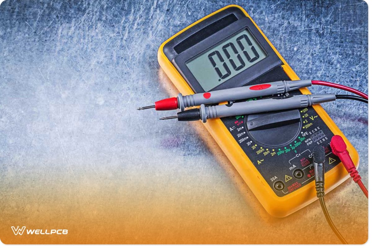
Figure 7: An Ohmmeter
When there is no triggering pulse at the MOSFET’s gate terminal, its drain-to-source resistance is high. The resistance test takes advantage of this property to test if the MOSFET is faulty. This test is also easy and requires only an ohmmeter to perform. The following are some of the fundamental steps of conducting the resistance test:
- A well-functioning MOSFET should indicate a high drain-to-source resistance irrespective of the connection of the ohmmeter probes. The polarity of the connection is, therefore, inconsequential to the outcome of the test.
- You can also use an ohmmeter instead of a multimeter to check the drain to source resistance. Put the multimeter on resistance mode to initiate the test. You should obtain a reading indicating an extremely high resistance. The resistance of a MOSFET is so high that this reading should be in megaohms.
- Compare the reading obtained from this reading with the MOSFET’s datasheet. If you find that the value of the resistance reading is less than what is on the datasheet or zero, it is faulty. The meter or ohmmeter should show the resistance which is on the datasheet.
Testing a MOSFET–By using an ohmmeter and multimeter in diode mode

Figure 8: MOSFET on a Motherboard
Testing the effectiveness of a MOSFET using this method triggers the device’s gate terminal. In turn, it prompts the drain to source resistance to go very low. The actual value to which this resistance drops depends on the type of the MOSFET.
You can trigger a MOSFET using a multimeter since the meter has a power source, usually a battery. Therefore, when you set the meter in diode mode, it will act as the MOSFET’s power source. Nonetheless, there are some precautions that you need to take.
You should ensure that the threshold voltage of the MOSFET is not too large. The threshold voltage should be within the range of the multimeter for optimum performance.
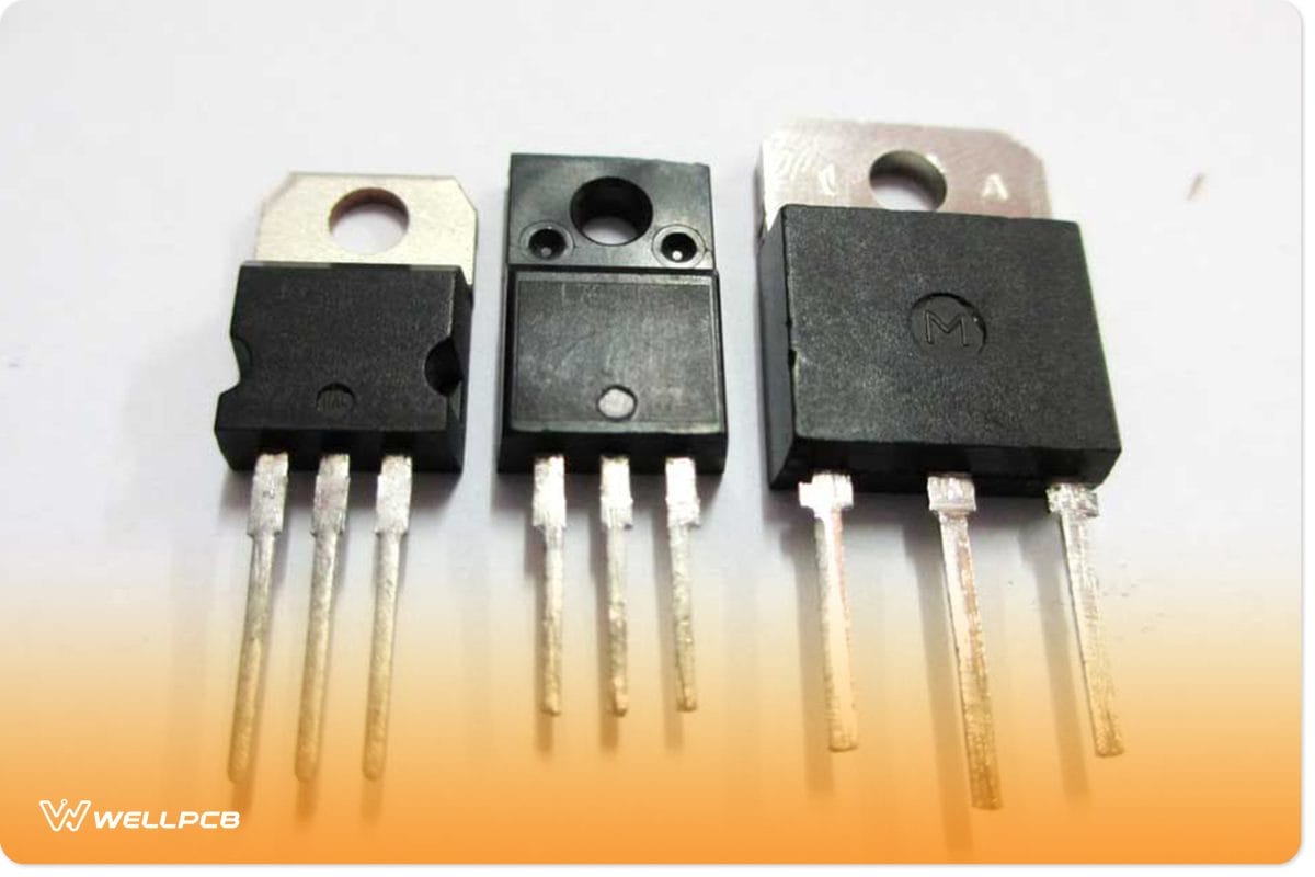
Figure 9: Different models of MOSFETs
The following are some of the key steps when performing this test:
- Use the resistance test to identify the drain to source resistance. It would help if you recorded the value of drain to source resistance of the MOSFET while in off condition. You will use this value for reference in the next step.
- Trigger the MOSFET. You will do this by first ensuring that the multimeter is in diode mode. Next, connect the black probe to the MOSFET’s drain and then place the red probe on the gate for a few seconds. This process will trigger the gate, and the MOSFET should turn on via this triggering.
- Using an ohmmeter, check the drain to source resistance of the MOSFET. You should expect a very low-value reading on the ohmmeter, which tends to zero in this step. If you obtain such a reading, the MOSFET is in good condition.
- Next, you need to check the MOSFET’s datasheet to confirm the drain to source resistance when the device is on. Compare the device’s datasheet value with your reading. If your reading is significantly different from the device’s datasheet value, the MOSFET is defective. Also, if your readings are the same as the read MOSFET in the closed mode, it has faults.
- If you find that the reading when the MOSFET is in on mode matches the datasheet value, you need to do further tests. First, discharge the MOSFET by shorting the drain or gate. You can use a finger or a jumper wire.
- Lastly, you need to test the drain to source resistance using the resistance technique. This reading should be similar to the prior reading of the device in off condition. If this is not the case, the MOSFET is in a malfunctioning condition.
Method 2:Testing a MOSFET–Using electronic components.
This method requires the assembly of a test circuit to test whether the MOSFET is functioning appropriately.

Figure 10: An electronic circuit board
This method assures you the most accurate results when testing the effectiveness of a MOSFET. You will nonetheless need to assemble a circuit first using these steps:
- Create a gate trigger pulse. The LED connected to the load will show you if the MOSFET is on or off.
- When the circuit is operational, the gate-to-source resistance of the MOSFET will act as the pull-down resistance. It will also cushion the MOSFET from damage through discharging the parasitic capacitance of the MOSFET.
- At first, when the push button is in the normal state, the drain to source resistance is too high. Thus, the LED should remain off while in this state, showing that the MOSFET is off. If the LED is on, this MOSFET is defective.
- When you press the push button, the drain to source resistance will go to very low levels. It should prompt the LED to go on, indicating that the MOSFET is on if the LED stays off while the MOSFET is defective in this mode.
- When you release the button, you will break the circuit, and thus, the LED should go off. If, after releasing the controller, the LED remains on, this MOSFET is also faulty.

Figure 11: Components of testing a MOSFET
There are several precautions that you need to undertake when testing a MOSFET. They include:
- You must ensure that the input power supply is greater or equivalent to the MOSFET’s threshold voltage.
- You should also not exceed the drain voltage and gate voltage of the MOSFET above the breakdown voltage.
- The LED that you are using requires approximately 20 mA. You should, therefore, choose a suitable current limiter resistor to power the LED.
- You should always use a gate to source resistance in your connections. It will help avoid noise at the gate while also facilitating the discharge of parasitic capacitance of the device.
- You should also always use a low range of resistors at the MOSFET gate. It should be approximately between 10E to 500E.
- Lastly, when testing via the test circuit technique, ensure that you use the low-side switching circuit. Otherwise, the MOSFET won’t work.
Conclusion
As highlighted in this article, you need to test whether a MOSFET is defective before using it. A faulty one can potentially bring loads of issues to the circuit.
We have laid down all the critical insights on testing a MOSFET. Thus, you are free to use any of the above techniques.
Any of these methods should work for you effectively without any hitch.
We are also committed to providing expert advice on MOSFETS and other electronic devices.
Contact us, and our team of experts will respond to your queries in the shortest possible time.
We are here to help you.