If you’ve ever wondered what controls those pulsing airport lights, you’ve come to the right place! The answer, a time delay circuit, presents many capabilities and applications. Essentially, a Timing delay circuit enables electricity to flow smoothly but in a delayed sequence. While benefiting specific environments, it also configures automated control.
At WellPCB, we offer an in-depth article on this topic. After reading this article, you will define a time delay circuit, how it works, and many applications. In addition to that, you will also learn how to build one! So let’s get started!
Contents
1. What is a Time Delay Circuit?
These electronic circuits delay an input signal for a few seconds or minutes. The functionality occurs when the switch circuit receives power. It will turn on after time passes. Delays ensure that an electronic circuit achieves decent performance. Otherwise, it could malfunction or sustain damages.
Time delays can also control power distribution to varying electrical components. For this reason, some circuits can perform multiple time delay operations. In such circumstances, this involves integrating an electromechanical output relay with controls.
2. How Does a Time-delay Circuit Work?
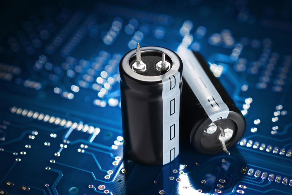
(A capacitor stores the energy)
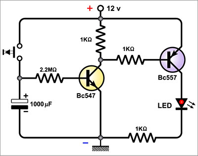
The circuit’s time delay effect occurs through a resistor and capacitor, which stores the electric charge. These operate together to indicate the capacitor’s charging time. In effect, this causes the delay. An integrated 555 timer along with passive components also helps to control the process.
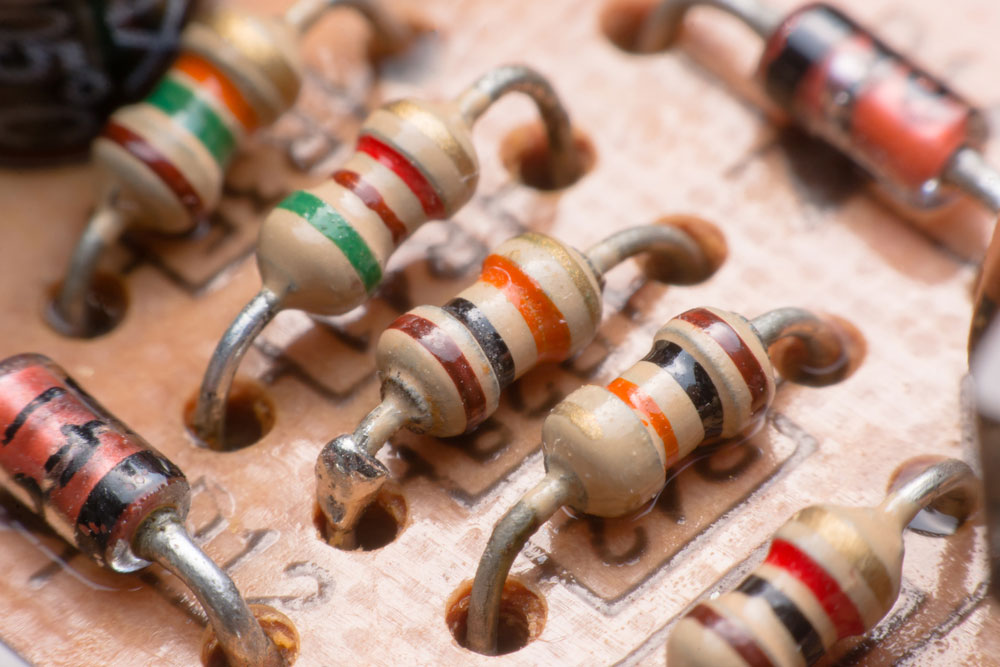
(Resistors with a capacitor to achieve the time delay effect)
While powering up, the trigger pin sets into a high state, preventing the circuit from running automatically. That particular non-charged capacitor solely causes this event. The pin will remain in such a state until the capacitor stores a full charge. However, the output only starts running when the pin reaches a low state. When the capacitor nearly reaches a full charge, the voltage at pin two lowers. Then, as the voltage supply approaches less than one-third full, the pin enters the low state. Finally, the output turns into a high state, causing the LED to activate. Usually, a circuit following this procedure takes seven seconds to power.
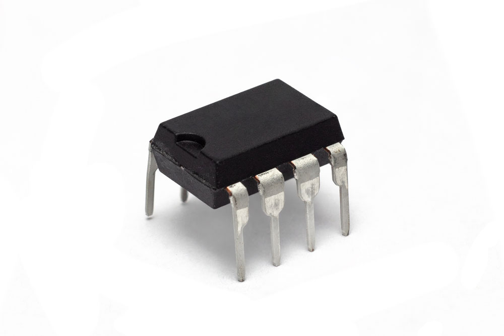
(Some circuits utilize a 555 timer for enhanced control)
If you’re using a higher-rated resistor and capacitor, then it will take longer to load. Contrary to this, a lower-rated capacity and resister shortens the delay time.

3. Building a Time Delay Circuit

(Building a timer switch circuit)
Components Required
You will need the following components to build a time delay circuitry:
- 12V Relay – 1x
- Transistor TIP122 – 1x
- LED – 2x
- 3.3V 1N4728A Zener diode – 1x
- 100k ohms variable resistor – 1x
- 1k ohms resistor – 3
- 330 ohms resistor – 1
- 1000µF F / 25v capacitor – 1
- 100µF F / 25v capacitor – 1
- 1N4007 diode – 1
The Circuit Design
First, connect one 1k ohms resistor, 100k ohms variable resistor, and 1k ohms resistor in series between the supply and ground. Connect the variable resistor’s wiper terminal to both the 1000µF capacitor’s positive end and Zener diode’s cathode.
Next, connect the Zener diode’s anode to the 100µF capacitor’s positive terminal. You also must connect this anode to the TIP122 transistor’s base.
Connect the 100µF and 1000µF capacitors and transistor’s emitter terminal to the ground. After that, connect one relay coil end to the transistor’s collector terminal and the opposite end to the supply. Add a diode between the coil ends. Take one LED and the current limiting resistor and connect them to the transistor’s collector. Place another LED to the relay’s normally open contact. Lastly, connect the com contact to the supply.
For proper use, a 12V relay for the circuit needs at least an 11V supply voltage.
Working Principles
This adjustable delay circuit’s functionality relies on the resistor/capacitor network. It also takes advantage of the 3.3V Zener diode. While energy flows to the circuit, the 100k Ohms variable resistor charges the 100µF capacitor. As soon as the capacitor charges to 3.3V, the Zener diode acts as a conductor.
The Zener diode causes the transistor to power up since it has a direct connection to the base. In effect, this also provides the relay coil with electricity. That’s because it connects to the transistor’s collector.
To prevent relay clicking, the 100µF capacitor that connects to the transistor’s base maintains a stable base bias. Next, both the 1000µF capacitor and variable resistor control the time delay. So far, the circuit performs short delays. A 12V relay provides instability if you require a longer delay. Therefore, this causes armature oscillations. A well-built circuit delays armature motion once the coil energizes, de-energizes, or both.
To make it more balanced for a longer delay, we recommend a 6V relay with a 100k Ohms resistor connected in series with the coil. For this reason, the armature operation stabilizes. Furthermore, a 20K Ohms variable resistor provides an eight-second delay.
4. Time-delay Circuit Applications
Time delay circuits provide numerous benefits with their delay capabilities. We outlined some example applications of time delay circuits below.
Flashing light control (time on, time off)

(Flashing lights in an airport)
It relies on two-time delay circuits to operate. Working together, these distribute sporadic power to a light fixture through the contacts’ continuous frequency on/off pulsing.
Engine autostart control
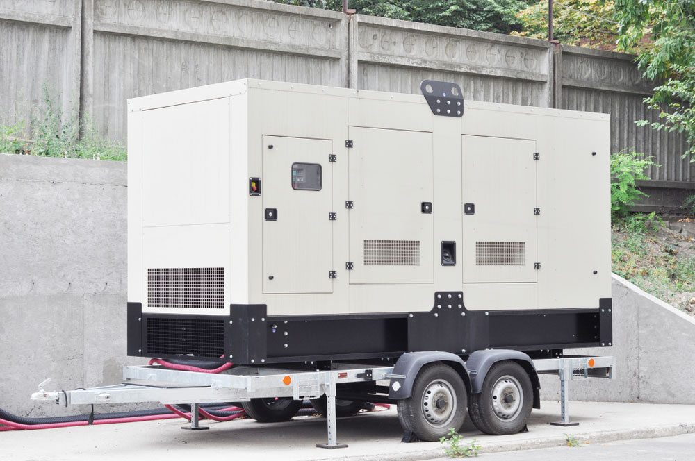
(Back-up generator)
A time delay circuit helps an engine run properly if power from the main source cannot deliver. Usually, these contain auto-start controls for backup generators. However, it doesn’t occur immediately. Fuel pumps and pre-lubrication oil pumps must start-up and stabilize before powering the starter motor.
Furnace safety purge control

(A combustion furnace relies on a time-delay circuit to cleanse the chamber)
Safely lighting a combustion furnace requires the air fan to operate for a certain time. When running, it cleans the chamber from any hazardous vapors. With an implemented time delay circuit, the furnace performs this necessary time control.
Motor soft-start delay control
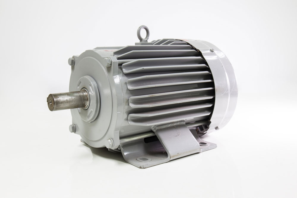
(Electric motors consist of integrated circuits to provide full power in a delayed sequence)
A dead stop condition usually provides an electric motor with immediate full power. Applying a lower voltage enables an improved startup sequence with a reduced current. Full power delivery occurs after a time delay via time-delay relay.
Conveyor belt sequence delay
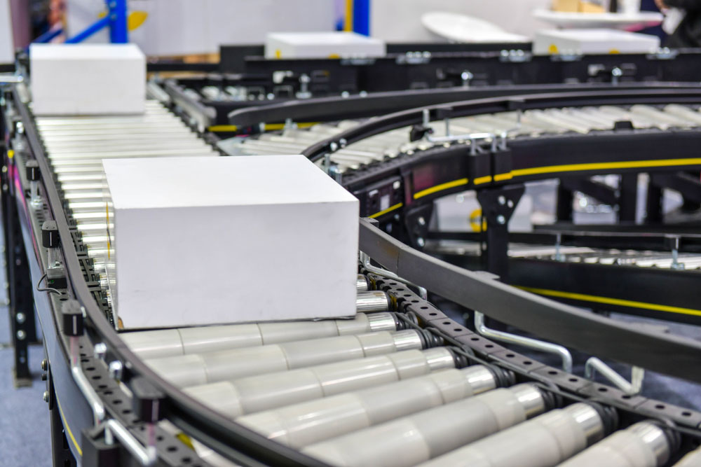
(Multiple conveyor belts need a time delay circuit)
Soft-start motor controls in conveyer belts require a time delay so they can operate at maximum speed. That’s because several conveyor belts delivering resources must begin operating in reverse order. It ultimately prevents a slow transition from one conveyor to the next. As a result, each conveyer belt equipped with a time delay circuit can reach full speed before the next one starts.
Conclusion:
Overall, a time delay circuitry presents many advantages. Not only does it delay a circuit from powering up, but it also provides safety measures for certain applications. For example, it prevents voltage spikes in the most efficient manner possible. Sometimes these take a few minutes to operate, but those usually occur in industrial workplaces. As we learned, a time-delay circuit utilizes an RC network to store and distribute power, contributing to the delayed effect. Therefore, this can occur anywhere from a few seconds to a few minutes.
Feel free to contact us if you have any questions regarding a time-delayed circuit!


