Contents
TIP31C Pin Configuration
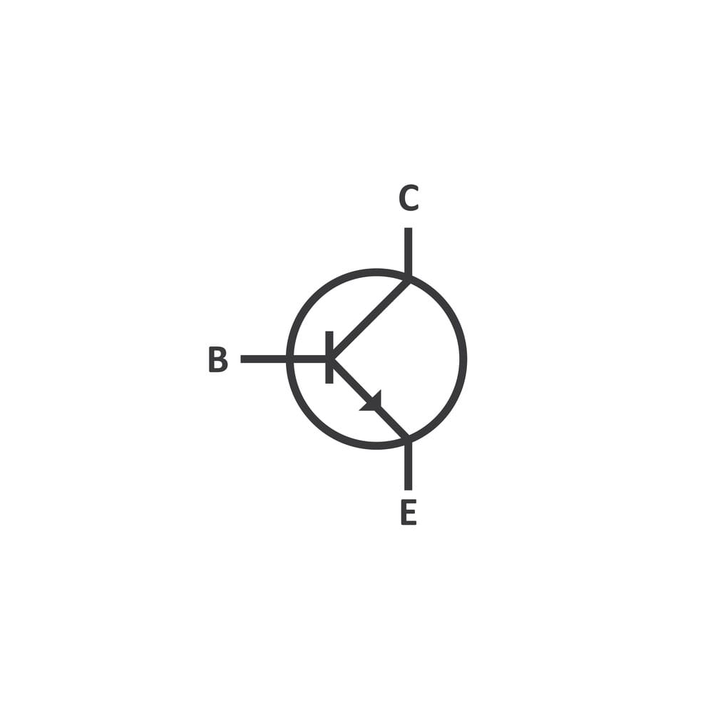
(The TIP31C NPN transistor structure)
TIP31C is a three-terminal NPN power transistor, with the package pinout below.
Pin1/ Base(B) operates as a trigger and consequently turns on the power transistor.
Pin2/ Collector (C) – It connects to the load.
Pin3/ Emitter (E) connects to the circuit ground (GND).
Features / Technical Specifications
TIP31C has several specifications and features that we’ll discuss.
- First, its package type is TO-220, and it’s a medium power transistor type.
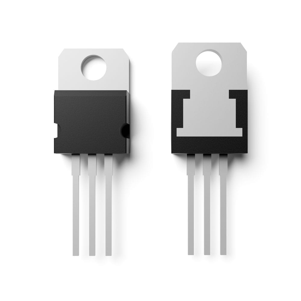
(NPN transistor in TO-220 package)
- Then, its maximum collector current (Ic) is 3A, while its maximum collector dissipation is 40 Watts.
- Its maximum current through the transistor base is 1AmpDC, whereas the maximum current through the transistor collector is 3AmpDC.
- Also, its maximum emitter-base voltage (VEBO) is 5V.
- In addition, the range of its minimum and maximum DC gain (hfe) is from 10 – 50.
- Its maximum collector-base voltage (Vcb) and maximum collector-emitter voltage (Vce) are both 100V.
- Lastly, its maximum storage and operating temperature should range from -65°C to +150°C.
Replacement and Equivalent
If you need a replacement of TIP31C or its equivalent, you can use the list here.
- MJE34C,
- TIP31A,
- TIP31B,
- RCA1C06,
- 2SB595,
- 2SB690,
- 2SA77,
- BD712,
- MJE42C,
- BDT42C,
- 2SA1010,
- 2SB633,
- 2N6134,
- NSP42C, or
- BD912.
However, before proceeding with the replacement, ensure you check the pin configurations and parameters of the equivalents. In that way, you’ll avoid any damages that may occur due to unmet gain parameters, current, and voltage.
TIP31C Transistor Description
TIP31 NPN transistor has a design for amplification, like audio amplifiers and general switching applications. As a result, it can drive several loads simultaneously and conduct fast switching as a switch.
What’s more, its availability is in four different types, namely TIP31C, TIP31B, TIP31A, and TIP31. While they may have a similar transistor number, they differ in voltages and the last alphabet. For example, TIP31C can withstand a higher load voltage. In addition, TIP31C can handle up to a maximum load voltage of 100V. We have cited its other capabilities in its features.
Where to use TIP31C?
We’re going to consider three situations to explain where you can TIP31C.
Example 1
In the first case, you’ll use microcontroller pulses to control TIP31C because it has a high speed and gain response. Therefore, TIP31C will favor high-speed switching applications.
Example 2
Secondly, you can use TIP31C to amplify signals. The NPN transistor has an almost linear gain and an excellent amplifying factor.
Example 3
Finally, TIP31C can switch devices with medium power loads. TIP31 is recommendable since it’s cheap and readily available in the market because of its popularity in electrical applications.
- How to use TIP31C?
Using TIP31C is similar to using any other power transistor. In our circuit below, we’ll show you how it works when we use it in a common emitter configuration.
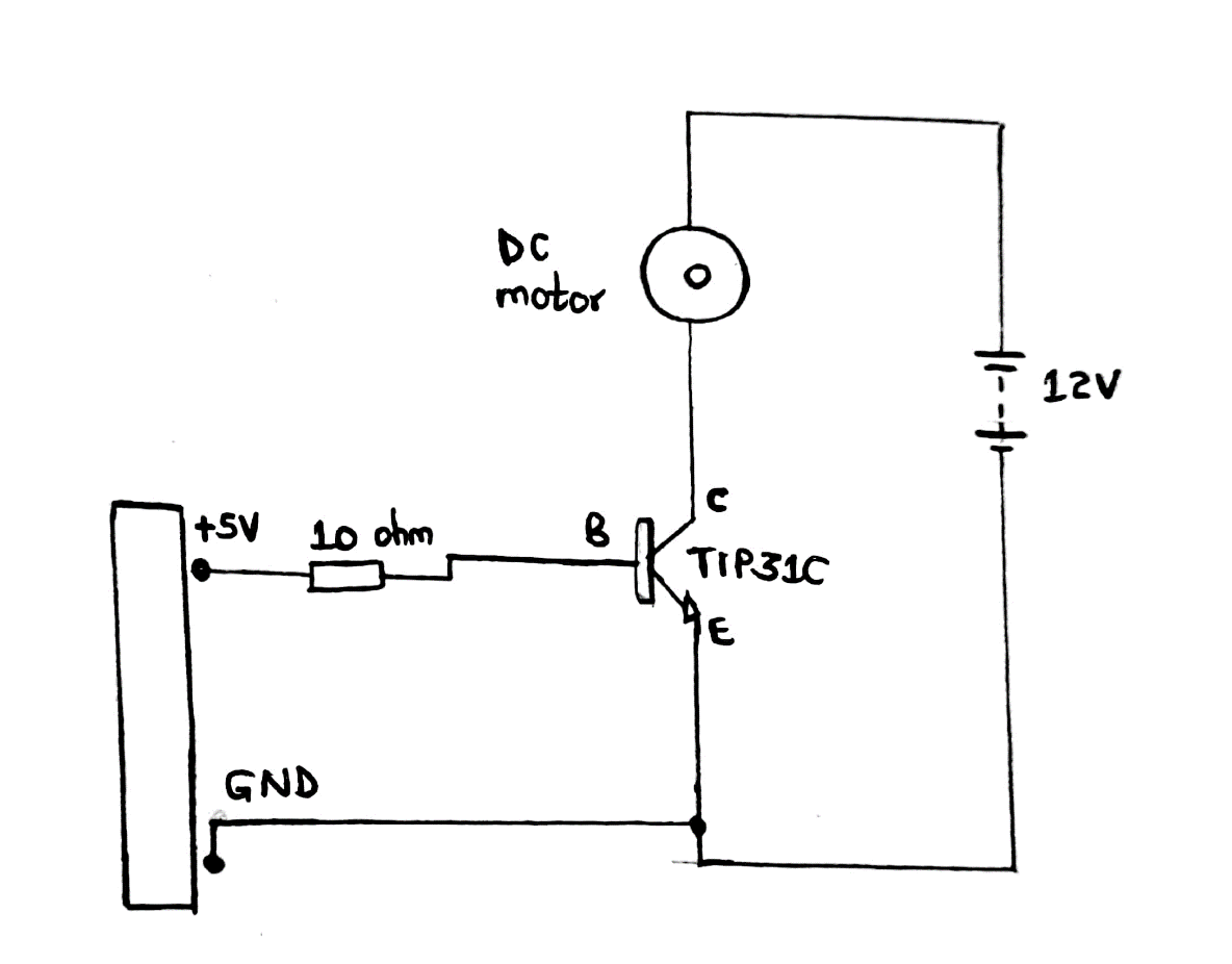
Circuit diagram of TIP31C as a simple switching device
From the circuit;
- We have TIP31C as a simple switching device.
- Also, there’s a small DC motor load.
- Then, the control unit, which isn’t a microcontroller, provides a trigger that turns on the transistor. It does so by producing +5 volts to the transistor base.
Note;
It is compulsory to connect the transistor emitter to the control unit ground for effective working.
The 10Ω resistor limits the current through the transistor base. Base current limiting is necessary, and you can choose a suitable value with the calculation below.
Max current through the base – 1 Amp
Base current – Can be 0.9 Amp
Max voltage across the emitter and base is 5V.
Vbe can be 4.5
The voltage across the R resistor is XX V (Control unit voltage output – 4.5)
Therefore, R = XX/0.9 = YYΩ (to be placed in series with the base as in the circuit)
Working principle of TIP31C as a switching device
Often, when there’s no base current, the transistor is off in the application circuit. However, if the voltage pulses of the control unit get to the base, current flows via the transistor base. Subsequently, the current flow switches on the transistor. In turn, collector current will also flow through the motor, making it rotate. The motor will maintain its rotation until there’s a base current.
Conversely, low control unit output causes the base current to be zero. Eventually, the transistor shuts down, the collector current becomes zero, and the motor stops rotating.
Please note that the circuit above is only a test circuit. When using an application circuit, remember to incorporate a flyback diode, heat sink, and other components to prevent damage.
Using TIP31C as an amplifier
We should consider the current gain characteristics of TIP31C as an amplifier. Thus, the current gain graph in a TIP31C datasheet will help better understand the concept.
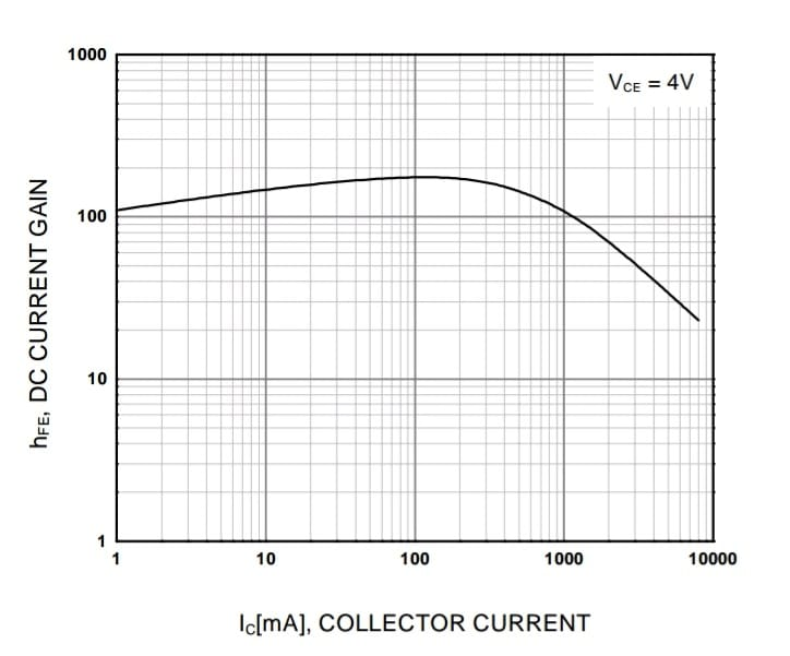
Current gain graph
The graph has a gain of approximately 100 and a collector current of 1A/100mA. Then, when the collector current is 2A/2000mA, the gain drops to 60. On the contrary, the above 2A of collector current results in a linear gain.
The range of parameters in the above example is effective for TIP31C as an amplifier.
Application
You can find TIP31C in the applications below
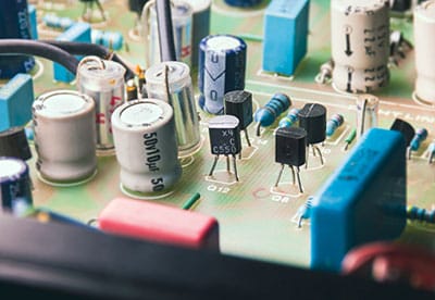
- Signal amplifiers,
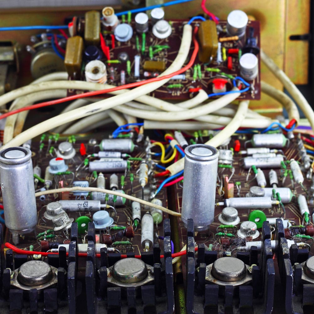
(circuit board of an amplifier)
- Relay drivers,
- DC motor speed control,
- Audio amplifiers,
- Lighting systems,
- Switch-mode power supply,
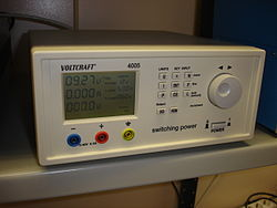
Adjustable switched-power supply for laboratory use
Source; Wikipedia
- PWM applications.
Conclusion
Briefly, TIP31C is a TO-220 packaged NPN power transistor. Moreover, it is suitable for switching, linear power, and audio applications because of its advantageous features.
For further inquiries or clarifications on TIP31C, kindly contact us. We’re always ready to help.