If a circuit draws in a lot of power, it will need a transistor to help regulate the current. However, an individual transistor may not perform the task sufficiently, so you may need to implement transistors in parallel. It improves the shared current handling capacity and provides many key benefits for your electronic circuit. For example, it prevents a transistor from sustaining damage, depending on your implementation method.
Understanding how it works can seem fairly complex. So let’s get started! At WELLPCB, we aim to guide you in the right direction. After reading this article, you will learn about parallel transistors and what it achieves.
Contents
1. What are Transistors in Parallel?
On a circuit, two transistors’ matching pinouts form a connection, known as parallel transistors. Achieving this boosts the amount of current capacity the transistors can handle. After implementation, you won’t need to worry about the transistors dealing with too much power.
2. Why Connect Transistors in Parallel?

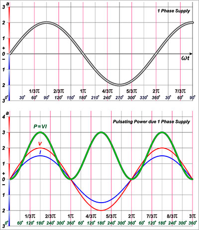
(A circuit will need transistors in parallel if it draws in a large amount of power.)
If you’re building a circuit that will draw in high output current, you will need to connect transistors in parallel. That’s because a single transistor cannot handle that amount of power, potentially leading to permanent damage.
Using this method helps to provide a current load balance. It occurs from distributing the power from one transistor, which remains undamaged, to the next instead. These two types of transistors can connect in parallel: BJTs or MOSFETs.

3. Implementing Transistors in Parallel With the Correct Approach
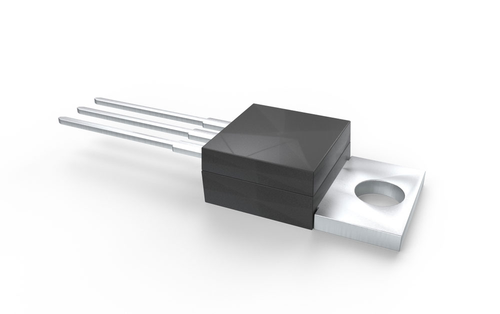
(MOSFETs in parallel provide high conductivity, which distributes current effectively.)
In this section, you will learn how to connect both BJTs and MOSFETs in parallel. If you connect bipolar transistors in parallel, you must integrate the ballast resistors in series, a common approach for audio amplifiers. Generally, it deals with high power consumption and involves interconnecting the bases and emitters together. And it solves current imbalance issues. The first two steps below demonstrate how you can calculate both the resistor’s Ohm values, allowing you to connect them in series.
Step One:
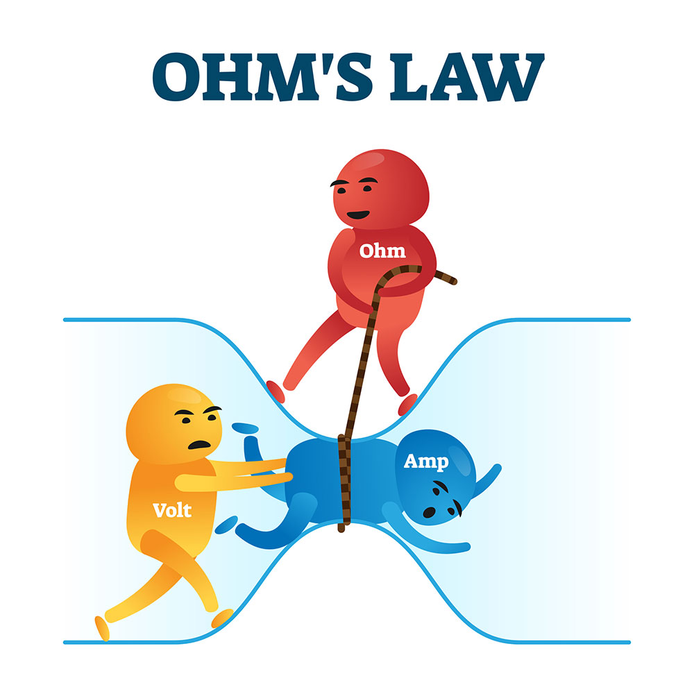
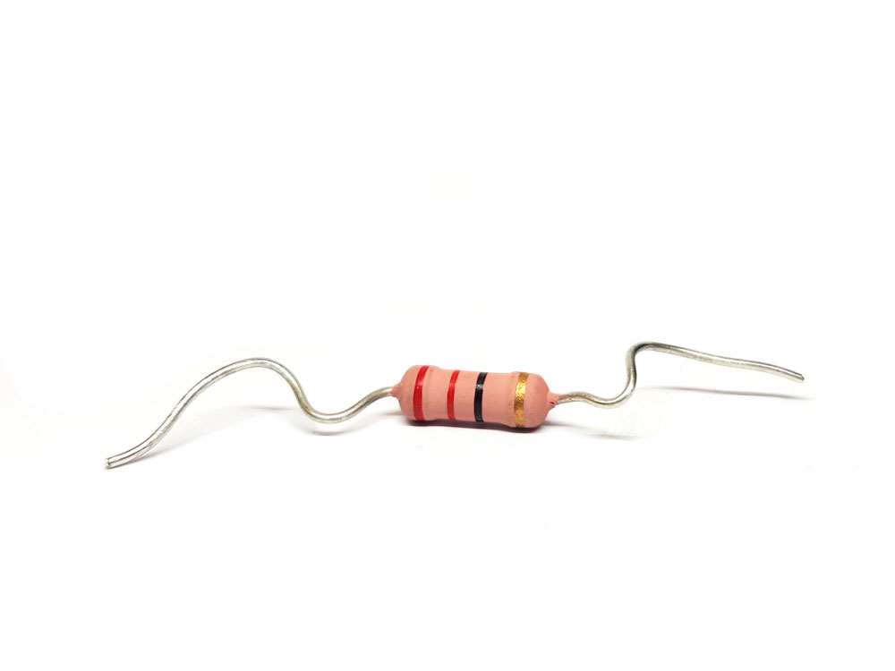
(Use Ohm’s law to calculate the resistor rating.)
First, you will need to perform calculations for the resistors. Use the R = V/I formula for the current limiting one. V serves as the circuit’s voltage. Meanwhile, the “I” value represents 70% of the amount of current the transistor stores. For instance, a 2N3055 BJT can store approximately 15A. So, 70% of that value equates to 10.5A. With a 12V supply, the calculation looks like this: R = 12/10.5 = 1.14. Therefore, the Ohms rating should reflect the 1.14 value.
Step Two:
(The base resistor helps to balance the current load on a transistor.)
Next, you will need to calculate the base resistor’s Ohms. Use this formula: Rb = (12 – 0.7)hFE / Load current. The hFE value equates to 50 while the load current sets at 3A. Finally, you can perform the calculation with: Rb = 11.3 x 50 / 3. The result equals 188 Ohms.
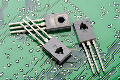
Step Three:
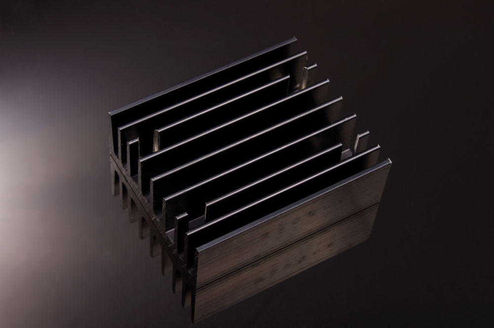
(You can place the BJTs over the heatsink to help with current handling.)
However, if you don’t want to implement resistors, you can install a heat sink instead. For this technique, just fit a standard heatsink underneath the BJTs and add plenty of thermal paste to each surface. It enables equal heat distribution while providing a solution to thermal runaway. Furthermore, the transistors easily connect in parallel via the heatsink’s metallic structure.
Step Four:

(An MOSFET with a gate resistor provides a safe and efficient solution, preventing thermal runaway.)
MOSTEFs can connect in parallel as well. While achieving this, you should implement a gate resistor with each device. However, some upsides keep it extremely safe and efficient. For example, when heating up, they turn less conductive and gradually prevent current flow. On the plus side, these don’t exhibit thermal runaway. These directly connect via drain to drain, gate to gate, and source to source.
4. Solutions for Transistors in Parallel Mistakes
Mistake 1:Thermal Runaway
Avoid method: Thermal Runaway occurs when one transistor in parallel mismatches the other transistors. Generally, this means that it will cause one transistor to draw in more current than the rest. From there, it collects more heat, which builds up until finally sustaining permanent damage.
To prevent this from happening, you must integrate a low-rated resistor connected in series with every emitter. For example, if the load equates to 50 Ohms, then a 1 Ohms resistor will perform well. It provides negative feedback that keeps the current moderated because of the voltage increase in its emitter resistor.
Mistake 2:MOSFET linear operation
Avoid method: MOSFETs normally perform well as a switch when connected in parallel. However, these do not distribute current under linear mode. That’s because heat build-up increases conductivity at a faster rate. Then, conductance will increase in frequency. In effect, that causes a hot spot to form, potentially damaging the MOSFET. It provides a worse problem compared to BJTs in parallel.
Additionally, transconductance increases when the device’s temperature rises. MOSFETs in parallel will not distribute current until it reaches 15A. These don’t usually reach that level when performing under linear.
The best solution to this problem involves utilizing a feedback loop on each MOSTEF current device. It allows more current control in linear operation.
Conclusion:
To conclude, this article mainly focuses on the correct implementation of transistors in parallel. Plus, we covered how you can avoid common mistakes that occur with BJTs and MOSTEFs. For example, BJTs should contain a resistor in series for current sharing. Meanwhile, adding a feedback loop on MOSTEFs prevents the device from undergoing damages. Additionally, you can integrate transistors in parallel with a heat sink, a more efficient approach compared to BJTs.If you have any questions regarding transistors in parallel, feel free to contact us!