Contents
1. What Is A Trimpot and How Does It Work?
A trimpot is the abbreviation for a trimmer potentiometer. It is an adjustable resistor commonly found in electronic design projects. Essentially, it works to provide fine control over output signal voltage levels, and in effect, it adjusts the total resistance values within.
When adjusting a trimpot or preset, you mount them onto printed circuit boards and reset them using a screwdriver. In the case of a trim pot serving as a rheostat, we regard them as preset resistors. The most common ones include the ceramic metal oxide composite (ceramic) and carbon composition (carbon).
Features of a Trimpot
A preset potentiometer has a couple of peculiar attributes. Some of the most common technical features include:
- Availability in carbon film or standard type.
- They exist in different values of resistance. From 500 ohms to 1K and up to 1M ohm variable resistance trimpots are available.
- Another distinctive feature is the maximum operating voltage, and the maximum voltage rating is 50V DC.
- Its rotational life is 20 cycles.
- Finally, it has a max of 300 volts in power rating.
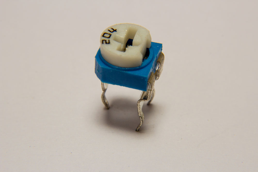
(Trimpot Image)
Other notable physical features of the regular trimpot are:
- It comes in a mini-sized package compared to the normal potter.
- Trimpots come in both single-turn and multi-turn.
- The electronic device has an adjustable interface made up of a rotor. Therefore, their design is automatic.
Trimpot symbols
Just like other specialized tools, engineers denote them by a peculiar symbol. However, many circuit diagrams label the trim pot, rheostat, and standard potentiometers alike. Nevertheless, there are still minor distinctions in their characters.
The Types Of Trimpots:Single-turnn and Multi-turn
There exist many different variations of trim pots. These versions also use different mounting techniques. In most, you have the SMD and through-hole methods. On the other hand, you have varied adjusting orientations. Here the adjusting knob is either on the side or on top.
However, there are two basic trimpot variations. They are:
Single-turn variation
Multi-turn variation
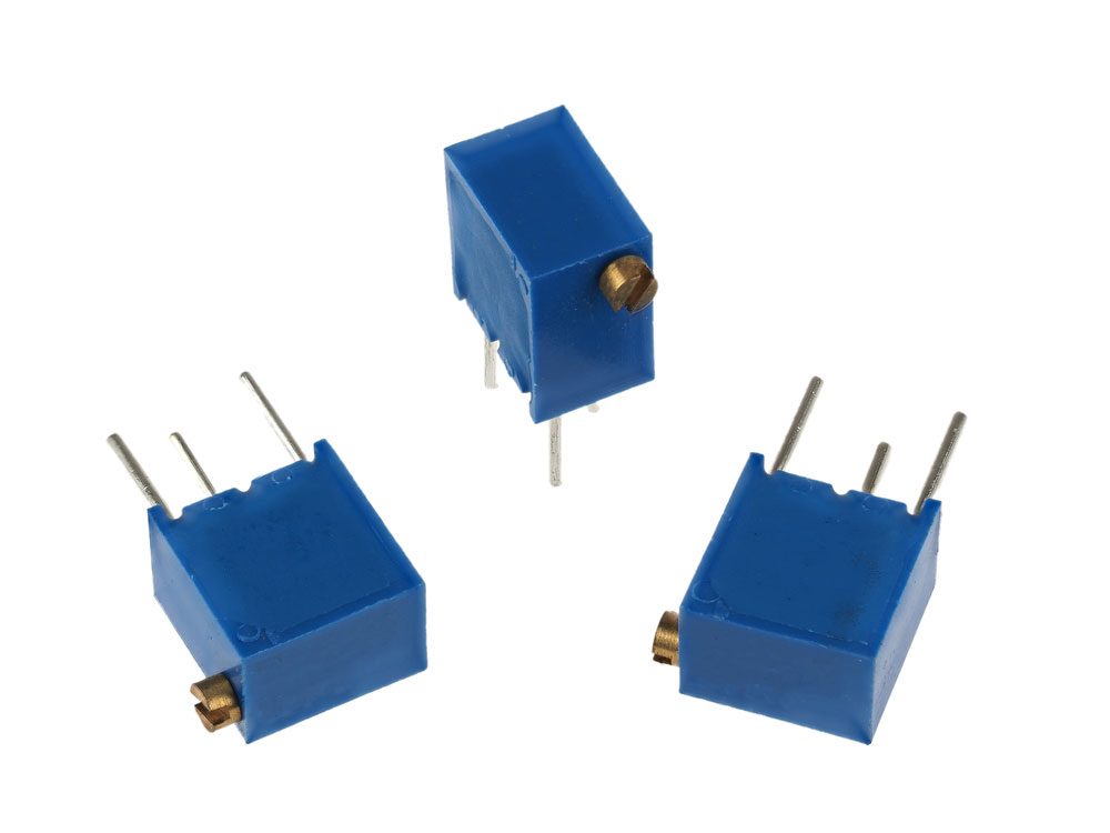
In the image above is a mix of through-hole, mountable, single-turn and multi-turn preset resistors.
Single-turn Variation
These types of presets/trimmers are more abundant in circulation. You apply this variation type in basic circuits where you need a single turn, and more so, you use them in lower adjustment resolutions.
Relatively, single-turn trim pots are the most affordable among the variable resistors.
Multi-turn Variation
Multi-turn trim pots are the more versatile option. You have different numbers of turns available to you. They range from 5 to 25 turns. Hence, if you need a higher adjustment resolution, then this variation is for you.
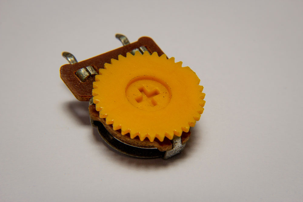
The construction of the multi-turn variation trimpot uses a rotary track (worm gear) mechanism. Others use a linear track (lead screw) construction pattern to reach respective high-resolution levels and power ratings.
Also, you get an increased power rating when you use the lead-screw type. This is a result of a larger surface area.
The Working Principle Of A Trimpot
The trumpet has the same working principles as the standard potentiometer. First, the end pins or terminals remain in a fixed position throughout. Then, the wiper shifts along the metal strip when you turn the knob of the trimpot.
Furthermore, if you turn the wiper such that it comes to rest close to an end terminal connected to it, there’s less resistance. This is because the path for current travel is now shorter. In the same way, if the wiper turns and rests far from the end pins, the resistance increases.
2. Trimpot Pinout Configuration
As an adjustment potentiometer, it comes with three pins. These three pins have specific configurations for different purposes, and their functions differ based on how you fix them in power connections.
- Fixed Terminal 1 (CW): This is one of the fixed points on the trimpot, connecting to one point of the variable resistor.
- Terminal 2 (Wiper): This is what connects to the variable knob on the trim pot. It helps provide varied resistance when adjusted. It connects to an LED or other output components}.
- Fixed Terminal 3 (CCW): With this, you have another fixed point that forms the other terminal of the resistive material.
(A trimpot pinout with all three pins shown)

3. How To Connect a Trimpot?
To use the trimmer potentiometer, you have to make the right connections. This involves setting it up in current circuits and placing the pins correctly on your PCB.
For pin placement, you pin the CW and CCW pins to the Ground terminal and positive supply voltage, respectively. You do this by positioning and mounting the pins directly on a breadboard or perf board. In effect, you get a variable voltage as output at the trimpot wiper terminal.
However, if you wish to change the voltage output, there’s a knob you turn on the trimpot. You find this control knob on the side or atop the miniaturized device. In turn, the resistance in the circuit varies as you turn that screw on the wiper.
(A screwing potentiometer used for electronics calibration)
4. Is Trimpot The Same As Potentiometer?
The answer is NO. For one, trimmer potentiometers are not regular resistors. So, they have unique working patterns. Yet, they differ in terms of how you connect them to a power supply.
The preset pots come in builds of smaller sizes than the potentiometer. Therefore, making it possible to mount them on a PCB or perf board.
By default, trimpots are not for users to control. Their primary function is to calibrate or fine-tune an electronic device after fabrication, unlike the standard potentiometer that allows variable resistance in a circuit.
5. The Applications Of A Trimpot
Trimpots are viable electronic components of both analog circuits and amp-type circuits. To mention a few, some applications voltage and current control circuits include;
- Controlling or tuning circuits.
- Temperature sensor devices.
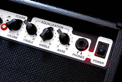
- Sound adjustment via the volume control knobs in radios.
- Functions as an analog input mechanism for control knobs.

(A significant application of trim pot is in audio control)
Final Words
In conclusion, the trimpot is still a type of potentiometer. Though built differently, it primarily adjusts the resistance in current circuits. So, it is classifiable as a variable resistor.
However, the trim pot is for specific fine-tuning and calibration purposes.
Hence, it has a limited turn cycle. For more on the preset potentiometer and its connection, please get in touch with us.


