Control and protection of electronic circuits is a critical process. For instance, consider a case where you want to manage current flow in a 10W LED bulb. In such an electrical circuit, you cannot just switch it on and off from a microprocessor, and you will require an electric relay for this operation. Read on for an in-depth analysis of the different types of relays and their operating principle. Also, for researched insights on the kind of relays and their applications, keep reading.
Contents
What is a Relay?
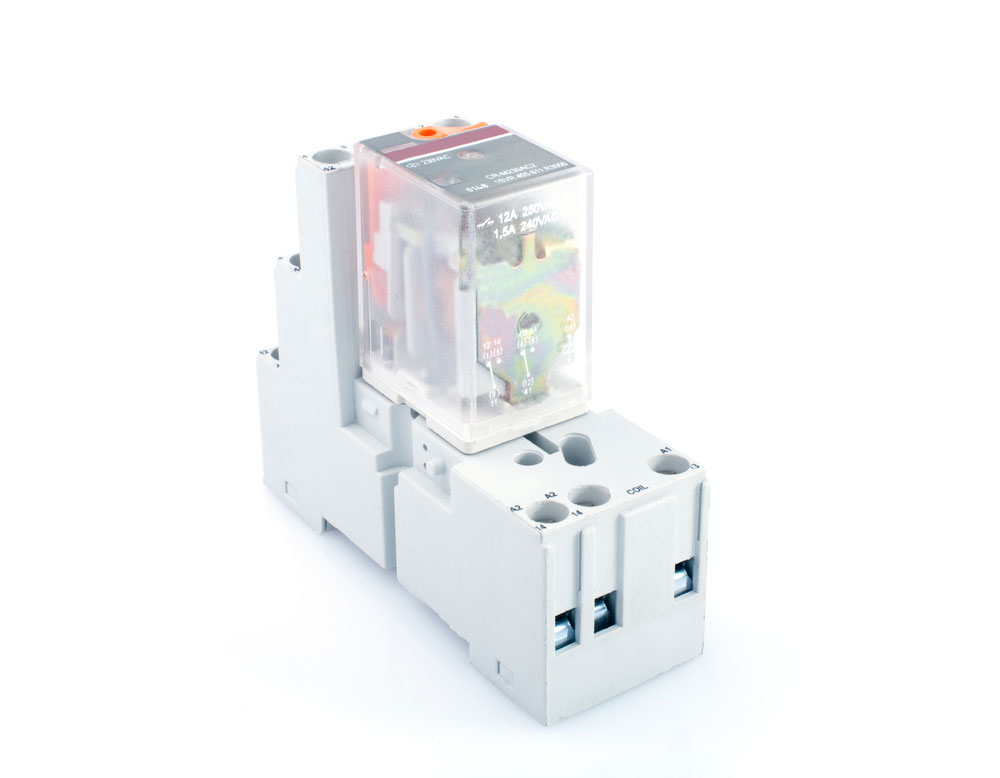
Figure 1: An Electric Relay Switch
A relay is an electrical switch that is useful in controlling high voltage circuits, and it uses a low voltage source to realize this function.
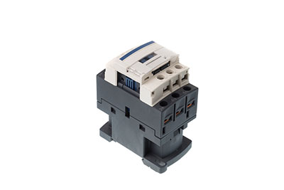
Basic Construction of a Relay
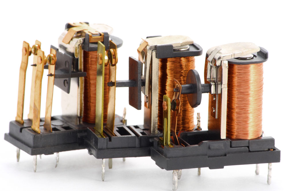
Figure 2: Electric Relay Switching
For the construction of a relay, it is essential to understand the internal parts of the electrical component. They include the following:
Relay terminals

Figure 3: Terminals For Connecting Wires
A relay has four main terminals Including:
Control Input or Coil Terminals
A relay consists of two input terminals that determine the switching operation of the component. During the process, you need to connect a common power source to the relay via these terminals.
The inrush current can be AC or DC.
Common Terminal (COM)
It is the component’s output terminal where you connect the load circuit.
Normally Open Terminal (NO)
As the name suggests, the terminal will remain open when the relay is inactive.
Normally Closed Terminal (NC)
It connects to the COM when there is no current input.
Poles & Throw
The two are the switches that you’ll find inside a relay. Poles are the actual number of buttons in a particular relay, and a throw is a collection of circuits that the relay controls for every pole.
You can have a single throw relay or a double-throw relay, depending on the circuits under control. The former is when the relay controls one course and the latter when it contains two circuits.
Types of Relay
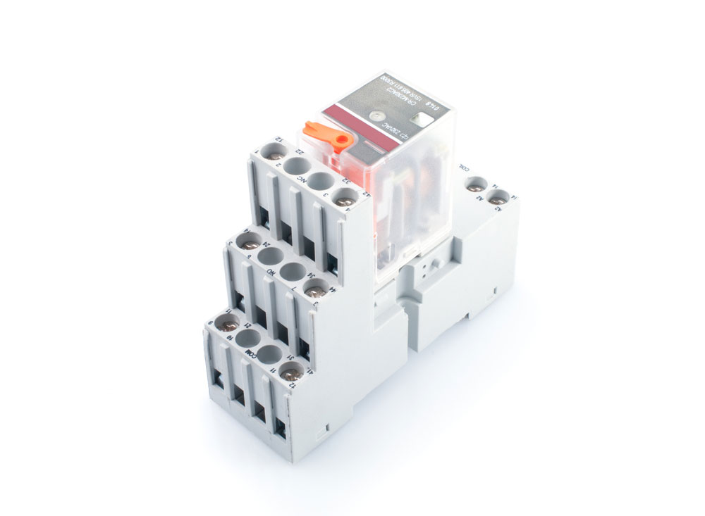
Figure 4: Electric Switching Relay
There are various types of relays, depending on their respective properties. Each class is helpful for a particular function. Thus, choosing a suitable relay is crucial for effective functioning in a specific circuit.

Based on Poles & Throw
SPST Relay(Single Pole Single Throw)
A single-pole relay controls only a single circuit. Also, since it is a single throw, the pole has only a single contact position. Thus, with this type of relay, you can either have an open or a closed circuit.
SPDT Relay (Single Pole Double Throw)
The relay is a single-pole type, so it can only control one circuit at a time. Nonetheless, unlike the other we have discussed above, this one has double throws. Hence, it will conduct from two positions.
Also noteworthy is that the relay has two states. Thus, when one circuit is in an open condition, the other remains closed. Also, when the formerly open circuit closes, the other opens.
DPST Relay (Double Pole Single Throw)
The relay is a double pole, thus capable of controlling two different circuits. But it is also a single pole, and hence, it will only conduct in one position.
The advantage of this relay is the ability to switch two circuits simultaneously.
DPDT Relay (Double Pole Double Throw)
The relay is a double pole hence will seamlessly control two circuits at the same time. It is also a double-throw, thus capable of conducting from two different points.
Having a DPDT is similar to having two SPDT relays but with simultaneous switching capabilities.
Also, note that a single relay can feature up to 12 poles.
Based on Forms
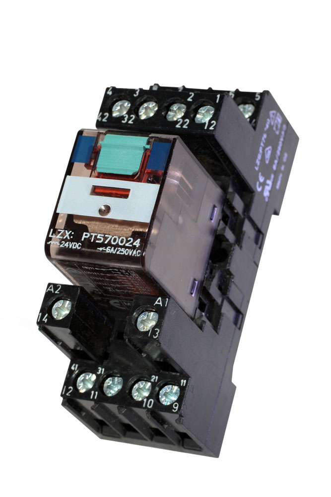
Figure 5: A Relay
Relays can also be categorized based on their forms. The following are the various forms and their respective characteristics.
Type of Relays– “Form A” Relay
Typically, you can consider the SPST relay in the normally open (NO) state as a form A relay.
“Form B” Relay
An SPST relay in the normally closed (NC) state is a Form B relay.
Type of Relays– “Form C” Relay
It is a term that refers to an SPDT type of relay. Remember that we earlier highlighted that this type of relay has two contact terminals.
Thus, it features an NC and NO terminal for controlling two circuits. It first prompts one of the circuits to open as the other shuts. Hence the name “break-before-make” relay.
“Form D” Relay
It is similar to the type that we have just covered. However, unlike the “Form C” relay, the “Form D” is different in its mode of operation.
It is a “make-before-break” kind. First, it will break one circuit then prompt the simultaneous opening of the other.
Thus, it works in the reverse mode of the “Form C” type.
Type of Relays– Based On Operation Principles

Figure 6: Relays in a Complex Circuit
Type of Relays– Latching Relays
The latching relays will maintain their state even after actuation. A static relay or impulse relay are some of the names that refer to these types of relays.
They are significant in applications aiming to control power consumption and dissipation.
It features an internal magnet. The magnet maintains the original position of the contact on the application of an electrical current. Hence, no power is necessary for maintaining contact in the usual place. Also, the removal of the drive current does not alter the contact position.
Therefore, the relay is significant in the conservation of energy in the control circuit.
Electromechanical Relays (EMR)
The relay features an electromagnetic coil and movable contact. The application of an electrical current on the coil induces a magnetic field. Consequently, the area draws the movable contact. When the magnetic field effect ceases to exist, the movable contact returns to its normal position.
The relay works for both AC and DC sources. However, a DC EMR will differ in structure from an AC EMR, especially regarding coil construction.
In a DC EMR coil, you’ll find a freewheeling diode that protects it from back EMR.
Also, note that the polarity of the EMR is inconsequential in its operation. However, with a back EMF diode, it is imperative to consider the polarity.
The primary downside of this relay is that it produces an arc in the breaking process, and the angle causes an increase in the relay’s resistance which is detrimental to its life expectancy.
Reed Relays
A reed relay is similar to the above discussed electromechanical relay. Nonetheless, it is slightly small in build and features a relatively lower mass, and it is essential in the creation of reed switches.
A reed relay consists of two strips of ferromagnetic material inside a glass tube with an inert gas. Energizing the coil results in the attraction of the strips to create a closed relay path.
Despite the slight differences with an EMR, the working principle of the reed relay is similar. Their operation will move a bimetallic strip type of contact to switch the circuit on or off.
Nonetheless, reed relays are faster than EMR relays in switching primarily because of the more minor contacts in the former. Also, since a reed relay lacks a moving armature, you will not experience a wear-out issue.
The presence of an inert gas also means it will prolong the lifespan of the relay.
Type of Relays– Buchholz Relays
The relays rely on gas as the medium of operation. They are significant in the detection of incipient faults in transformer protection applications.
Also, they’re heavy-duty relays, and you’ll find them in transmission and distribution systems.
Solid State Relays (SSRs)
Unlike the other relays we’ve covered made of mechanical components, these relays comprise semiconductors. Thus, you can expect to find details such as MOSFETs, TRIACs, and BJTs.
A solid-state relay will isolate a low voltage circuit from a high voltage circuit via an optocoupler. When you apply a control input to the relay, it lights up an infrared LED bulb. A photosensitive semiconductor device will convert the light to an electrical signal.
In turn, the control signal will switch the circuit.
The fundamental upside of this electronic relay is that it consumes lower power than the typical EMR. It is also relatively faster than an EMR relay due to the lack of mechanical contacts. Additionally, it features a longer lifespan. Also, solid-state relays do not have physical contact, and thus, there is no risk of burnout.
Hybrid Relay
It is made of electromechanical relays (EMR) and solid-state relays (SSR). Nonetheless, remember that an SSR will usually waste power as heat. Also, an EMR is capable of having a contact arching problem.
The hybrid relay solves the two problems via having the SSR and EMR in a parallel orientation.
During operation, there is a relay control circuit that first switches on the SSR. Thus, the SSR takes the load current, which is critical in eliminating the arching issue.
Next, the EMR energizes the EMR while also closing the contact. However, there is no arching in this process as the SSR takes care of the problem. Thus, the EMR will operate without any significant loss in the load current.
Hence, mixed relays operate as protective relays.
Type of Relays– Electrothermal Relay (Thermal Relay)
The relay comprises a bimetallic strip and exploits the difference in the expansion of the strips. As the current passes through the relay coil, it produces heat. The heat expands one part of the bimetallic strip, prompting it to bend, closing the contact.
In most cases, thermal relays are standard in electric motors.
Polarized & Non-polarized Relay
In a polarized relay, there is a permanent magnet that functions in coordination with an electromagnet. The function of a permanent magnet is to hold the armature position in a fixed state. On the other hand, the electromagnet will move the armature.
On the other hand, a non-polarized relay does not have a permanent magnet, and it is also easy to energize it.
Type of Relays–Application Of Relay
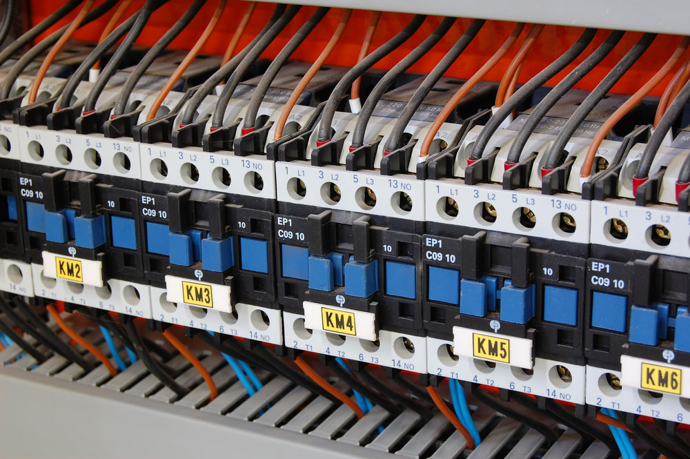
Figure 7: On and Off Switches
- Useful in the isolation of a high voltage circuit from a low voltage circuit.
- Control the flow of current in multiple circuits
- Facilitates automatic changeovers
- Useful in microprocessor control of heavy electrical load
- An overload relay is important in motor overload protection
Conclusion
Now you have it all. We have elaborated all there is to know about delay relays, and we have also highlighted how you can use them in a circuit board.
As you choose the relay to use, be guided by the switching time and type of light circuit. In addition, don’t be hesitant if you have any questions about switching current. Talk to us, and we will respond promptly.


