Contents
What is an Ultrasonic Fogger?
A fogger is a device that creates fog or mist. Now, ultrasonic foggers are a type of fogger that makes fog by ultrasonic oscillations.
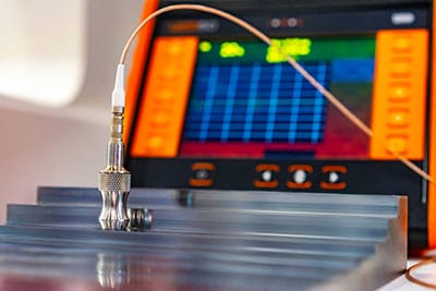
Ultrasonic fogger
Source: Wikipedia
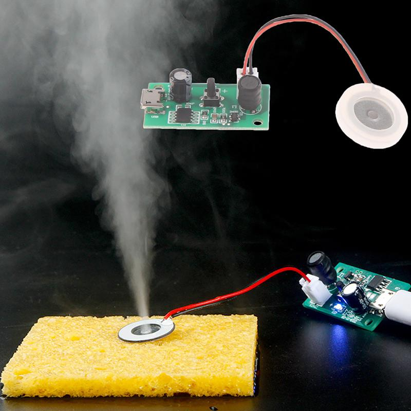
When you place an ultrasonic fogger in a bucket of water, the high-frequency ultrasonic oscillations break the water into billions of tiny water droplets. Then, the piezo atomizer disc immediately and continuously throws the particles into the air, forming a mist or fog.
How to Make an Ultrasonic Fogger Circuit
Materials you will require
- 2.4MHz Piezoelectric transducer, also called ultrasonic mist maker
- 40w to 60w Soldering iron
- A Circuit board
- 3.5 mm Dc jack socket
- Soldering wire, which has flux
- A potentiometer
- 24v wall adapter
- A beaker
- 22uH Inductor
- Bu407 NPN transistor
- Jumper wires
- 100pf capacitor
- 47nf capacitor
Procedure
- Start by soldering your Bu407 NPN transistor on the circuit board.

Circuit Board
- Then, on your NPN transistor base, fasten a resistor (3.9 ohms, to be precise).
- Next, bind the 100pf capacitor in the middle of the circuit board base next to the transistor collector.
- In the space between the transistor emitter and the 3.9-ohm resistor, affix a 47nf capacitor.
- Link your 22uH inductor coil right on top of the transistor emitter.
- Solder a 1nf capacitor in the middle of the emitter and the collector of the Bu407 NPN transistor.
- Place the 100-ohm resistor onto the 3.9-ohm resistor you fastened earlier on the transistor.
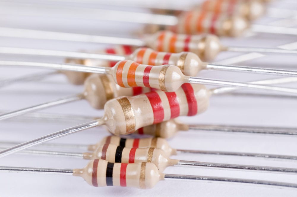
Resistors
- To adjust and preset the 100-ohm resistor, you will have to link a 5k pot to it.
- After which, you connect a 4.7k resistor in the middle of the circuit ground(GND) and the 5k pot.
- In the space between the transistor collector and 5K pot, affix a 3.3k resistor.
- Place the 4.7k nf capacitor right down the middle of the 100-ohm resistor and 3.9-ohm resistor.
- Using your solder, connect the positive terminal of the 2.4mh piezoelectric transducer to the transistor collector. Then, link it to the 47nf capacitor’s negative terminal on the driver board.
- Link the negative terminal leading to the 22uh inductor coil with the positive terminal of the direct current (DC) socket found on the transistor collector.
Below is a circuit diagram you can follow for more guidance when making your ultrasonic circuit or mist maker.

Ultrasonic Atomiser Circuit
Source: Best Controller Projects
Where
TD – Piezoelectric transducer.
L1 to L2 – Inductors.
C1 to C6- Capacitors.
Q1 – Transistor.
R1 to R6 – Resistors.
Working Principle
Place the piezoelectric transducer at the bottom of a basin full of water that you want to be ultrasonically atomized.
After which, the (DC) direct current obtained from rectified AC( alternating current) voltage passes through the electric circuit to the piezoelectric transducer.
The piezoelectric transducer then switches, turning the released high-frequency oscillations (sound waves) into mechanical energy.
This mechanical energy then piezoelectrically directs to the water, manufacturers stationary waves.
When the water passes through the Piezo disc’s atomizing surface, the discs fragment into uniform micron-sized droplets that form mist or fog.
Usually, when you place a variable resistor used to adjust fog or mist amount in the middle of a base circuit and resistors R2 to R3 junction, they will make noise.
Hence, capacitor 4, inductor L3, and transistors Q1 base circuit work as silencers against such noise.
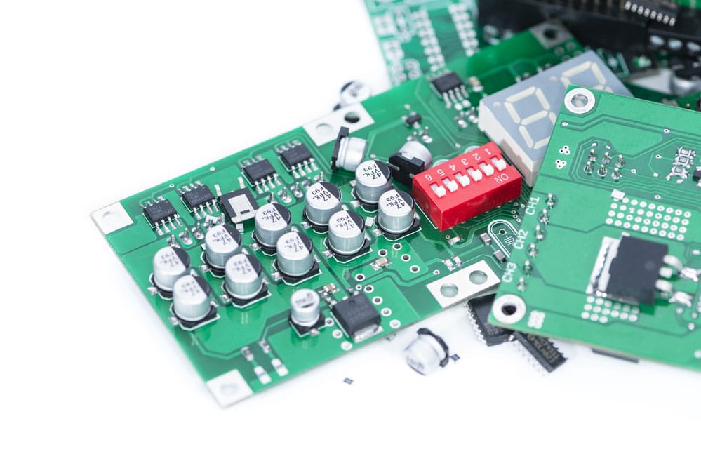
Circuit Elements: Transistors, capacitors, inductor
Precautions to take when making an Ultrasonic fogger circuit
- Ensure you follow the circuit diagram directions to the latter to avoid circuit failure.
- Always turn off your soldering gun when not in use to prevent burns.
Precautions to take when using an Ultrasonic fogger
- Avoid touching the ceramic discs when the fogger is still running, for they have an electric current passing through them.
- Ultrasonic transducers will vaporize all components in the water. If there are harmful chemicals in the water, they will be vaporized and released into the air. So only use purified water, and keep it clean always.
- Ensure you fully immerse the ultrasonic fogger(piezo speaker) head in water; an ideal depth is between 45 ml to 80 ml.
- Occasionally clean the inner disks and permanently replace them once you notice a decrease in the mist produced.
Advantages of ultrasonic foggers
- Cost-effective
- Long-lasting
- Easy to use
- Have Numerous Applications
- Simple to design
Applications of ultrasonic foggers
- TV Shows
- Movie productions
- Live concerts
- Home decorations
- Hydroponic systems
- Aquaponics systems
- Germination rooms
Summary
You can see why ultrasonic foggers have become critical players in entertainment and other sectors such as farming and home decor. Plus, the list keeps getting longer.
To fully maximize and utilize an ultrasonic fogger, take all the necessary precautions stated above in the article. Doing so will ensure your fogger serves you for a long time.
That wraps up the article, but you can always contact us for any inquiries you might have.


