Contents
Voltage Boosting Circuit Design
This setup is a simple circuit that receives a low voltage input of about (3 to 9 volts) and produces 100 to 200 volts.
But it’s crucial to note that you can’t use this circuit to power anything. And that’s because the voltage is across the capacitor. As a result, the voltage decreases rapidly with loading and the circuit shocks.
So, the components you need for this circuit design include the following:
- Inductor/ choke coil (L1) – 1
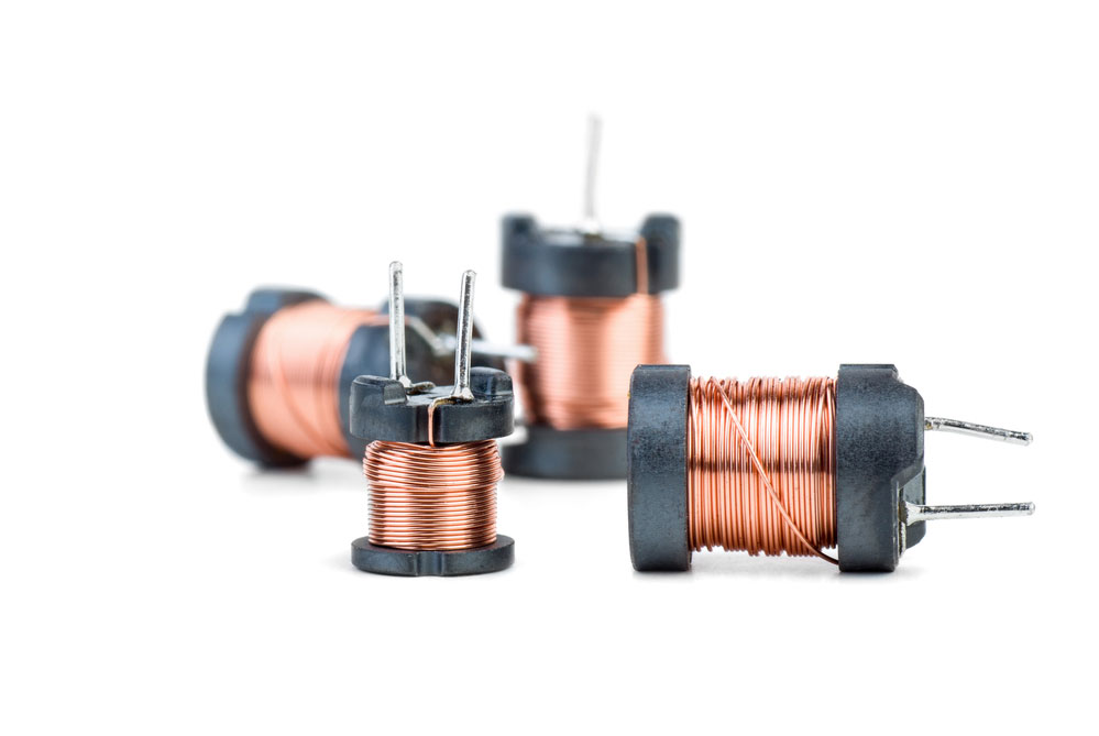
Inductor coils
- Tape – (1)
Tape
- Perfboard – (1)

Perfboard
- Breadboard – (1)
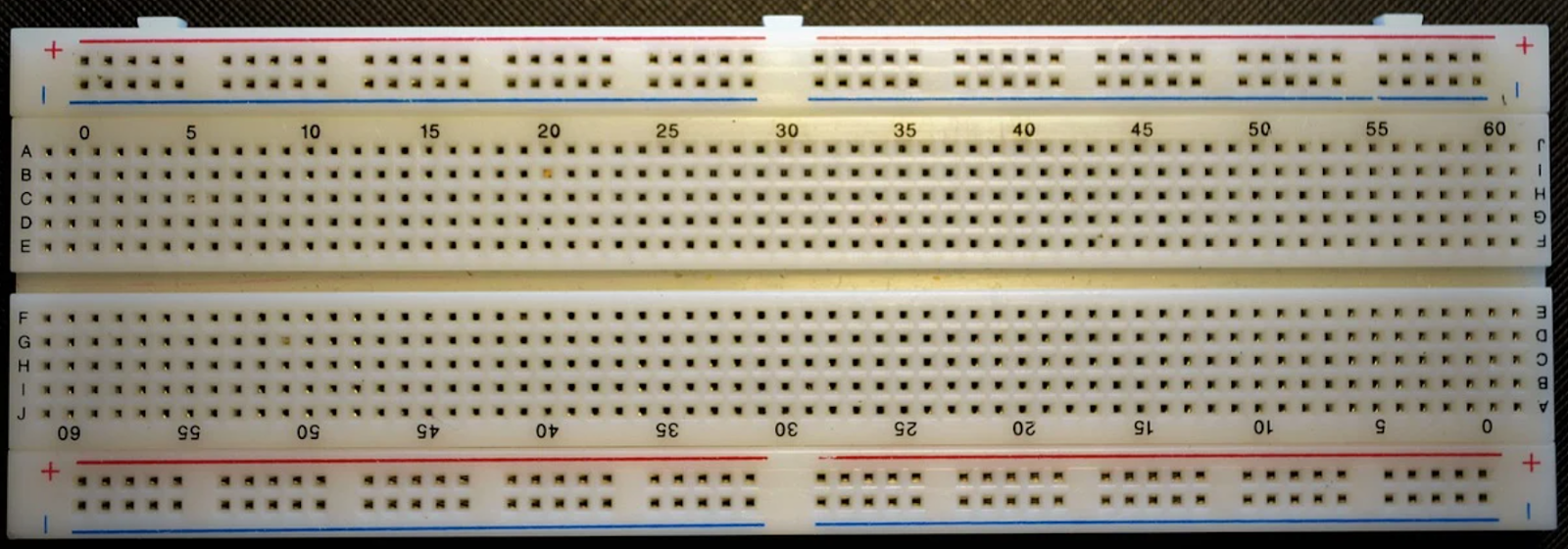
Breadboard
Source: Pixabay
- 2N6292 NPN Power BJT (Q1) – 1
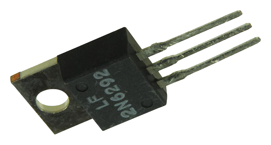
2N6292 NPN Power BJT
Source: Pixabay
- NE555 (U1) – 1
- Diode 1N4007 (D1) – 1
Resistors
- 1KΩ (R1) – 1
- 100Ω (R2) – 1
- 1KΩ (R3) – 1
Capacitors
- 100µF electrolytic capacitor (C1) – 1
- 10µF electrolytic capacitor (C2) – 1
- 10µF electrolytic capacitor (C3) – 1
- 2.5µF electrolytic capacitor (C4) – 1
Step 1 – Understand the Theory
Interestingly, this voltage booster circuit design has two circuits.
The first is a boost circuit consisting of a diode, capacitor, inductor, and switch. So, when the button causes the inductor to change in current quickly, it results in a significant voltage going across.
Consequently, the voltage generates large current flows, which charge the capacitor. But the diode stops the capacitor discharge. Hence, the voltage keeps building up.
The second circuit is the switch. And you can use a BJT power transistor 2N6292 alongside a 555 timer. So, the 555 timer functions to produce a square wave that turns the transistor off and on.
Step 2 – Measure Your Circuit Component
If you have any choke coils lying around, they’ll come in handy for the circuit. But before you use it, measure the internal resistance with a multimeter. And your value should be about 120 ohms.
Alternatively, you can get a high-voltage capacitor from a ceiling fan.
Also, it’s part of the single-phase induction motor circuit.
So, the capacitor has a 440v rating, and the diode remains the standard 1N4007.
Step 3 – Get Your Parameters
You can use the BC547 transistor for the switch. But you may not get good switching action. So, you can use the 2N6292 NPN power transistor instead. Consequently, your square wave generator should have the following parameters:
- Frequency – 4.85Hz
- Cb – 10µF
- Duty cycle – 66.74%
- Ra – 1K
- Toff – 69.53ms
- Ca – 100µF
- Ton – 69.22ms
- Rb – 1K
If you’re using a choke coil to produce your high voltage, ensure that your rated frequency is approximately 50Hz. But if the high voltage isn’t building up, you can try switching it on and off manually.
With this, you should have an excellent high voltage of approximately 200V built up. And you can set up your 555 timers to imitate the speed of your manual switching.
Step 4 – Build Your Circuit On a Breadboard
Set up the circuit on the breadboard first to ensure that everything works. And if the course doesn’t work, you can troubleshoot.
Most times, the fault may be from the switching circuit. So, if that’s the problem, start by changing your transistor. Then, you can also tweak your 555 timer frequency—till you get the preferred high voltage.
Step 5 – Do Your Design and Solder
While you’re at it, ensure that you solder the components carefully. You can use an Eagle cad to fix your details in this step. That way, you’d know where to put the jumpers. So, you can refer to the images while you are soldering.
After soldering, place your perfboard on the choke coil and hold it with tape. Then, place the capacitor on the choke coil as well. And connect the wires with screws to the choke. Interestingly, the circuit’s central shape and weight come from only the choke coil.
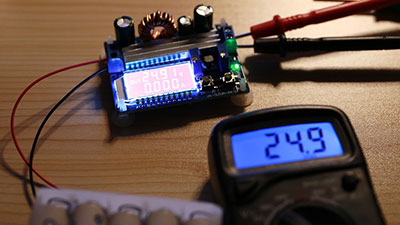
Step 6 – Test Your Circuit
You can test your circuit by setting up a multimeter. While you’re at it, try your power supply to measure its output voltage. Then, turn on your course. So, if you don’t hear any sound, something is wrong.
But if you hear the faint sound of a pendulum (tick-tock), it signifies that your choke coil works. So, you can connect your multimeter and set it at 200 V. Consequently, you should have an output current of over 190 V.
And you may also notice a wild fluctuation, but your voltage should remain high. With this, you can discharge your capacitor by shortening the output terminals. As a result, you may see a spark.

Applications of the Voltage Boosting Circuit
- Adaptive control applications
- Self-regulating power supplies
- Microwave ovens
- Lighting systems
- Hybrid electric vehicles
- Solar chargers
- smartphones
- Neon signs
- High audio systems
- Broadcast transmitters
Closing Words
The building or designing of a voltage booster circuit isn’t rocket science. All you need to do is to get the required components. Then, follow the working principle we’ve shown you in this article, and everything should work! You can use the voltage-boosting circuit in the following applications:
Also, we’d like to point out that a DC convertor is equivalent to an AC transformer. Plus, it has a constant adaptable turn ratio. So, it works like a transformer that equally steps up or steps down a voltage source.
Moreover, the DC booster converter also doubles as a switching mode regulator.
Do you need help building or getting a suitable voltage booster for your projects? Please feel free to contact us.


