Contents
What is a Voltage Doubler?
A voltage doubler is a voltage multiplier circuit with a multiplication factor of two. It takes in AC voltage as input, then produces DC voltage that is equivalent to twice the peak input voltage.
By doing so, the circuit does two things. It takes up the role of a step-up transformer by raising the peak AC voltage and a rectifier because it converts AC to DC.
Voltage doubler design
Since they are voltage multipliers, doublers make up the basic building blocks or single stages of higher-order circuits.
Voltage quadruple (note the four diodes and capacitors)
You can cascade similar stages to create voltage triples, quadruples, and more. A triple voltage has three diodes and capacitors, while a quadruple has four each. The circuit can scale upwards to reach whichever voltage you need for the project.
How Does a Voltage Doubler Circuit Work?
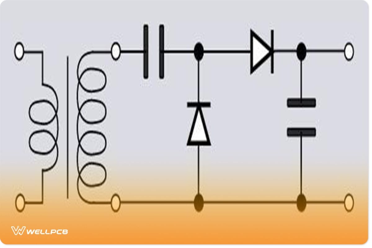
A voltage doubler features four discrete components that amplify the voltage and make the current flow in one direction. These are two diodes and two capacitors.

Voltage doubler circuit
The circuit arranges the components to make one of the diodes a conductor during each AC voltage cycle. In the positive half cycle, diode two remains off, so only one capacitor gets charged to the AC peak input voltage.
Diode one turns off during the negative peak, but diode two conducts and charges the second capacitor. However, the circuit had already charged capacitor one in the previous cycle. Therefore, this voltage gets added up to the incoming AC voltage.
The result is a doubling of the peak AC voltage source at the second capacitor, but this time as DC because the current will be flowing in one direction.
As such, a doubler acts as a charge pump, delivering 2Vin.
Types of Voltage Doubler
- Half Wave Voltage Doubler
- Full Wave Voltage Doubler
Advantages of Voltage Doubler
- A cheaper and lighter alternative to transformers.
- It can create negative voltage by reversing the polarity of the connected diodes and capacitors.
- Easy to increase the voltage multiplication factor by cascading identical voltage doublers in the circuit.
DC Voltage Doubler Circuit
Here comes the best part. If you want to build a DC voltage doubler circuit (half or full wave), you need the following components:
- Printed circuit board (or breadboard and connecting wires)
- Two diodes
- Two capacitors
So, how does the circuit work? In detail, let us look at both the half-wave and full-wave DC voltage doubler circuits. But first, here is how the input flows in.
AC Input Voltage
Since the AC waveform has positive and negative half-cycles, the explanation below describes what happens in these two cycles only. The doubling occurs repetitively as the power flows into the circuit.
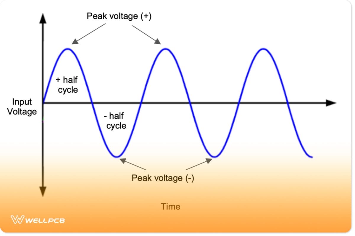
AC waveform showing the continuous positive and negative half-cycles
Vm is the peak voltage, and Vin is the input voltage. Vm = Vin at peak voltage, so we will use Vm in the equations.
Half Wave Voltage Doubler
With the polarity being as shown in the diagram below, the input voltage reverse biases diode D2. Its N side connects to the positive terminal, while the P side connects to the negative terminal of the AC source.
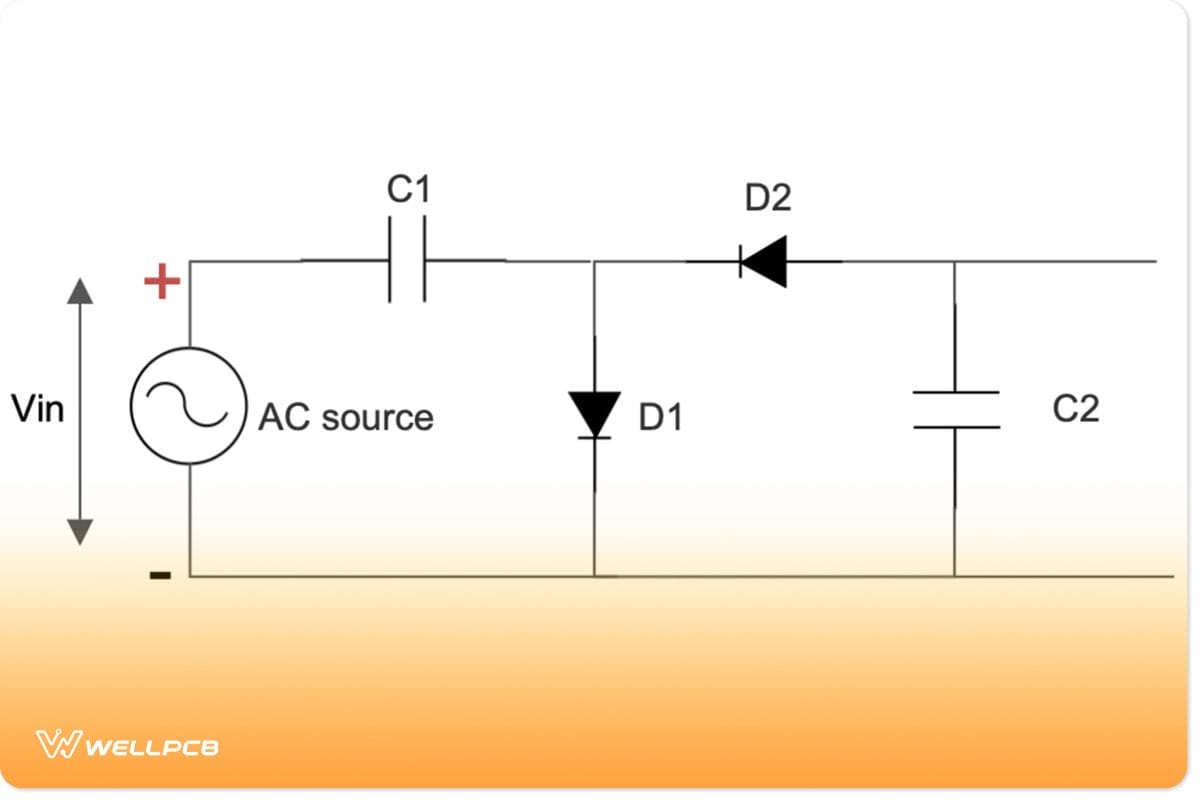
Half-wave DC voltage doubler circuit polarity during the positive half-cycle
On the other hand, D1 gets forward-biased because its P and N sides connect to the positive and negative terminals, respectively.
Therefore, you can reimagine the diagram as having diode D1 forming a short circuit (conductive joint) while D2 is an open circuit. You can use Kirchhoff’s voltage law to obtain the voltage across capacitor C1 (Vc1).
Vm – Vc1 = 0
So Vc1 = Vm
During the negative half-cycle, the polarity changes, as shown below.
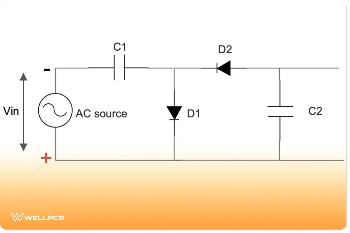
Half-wave DC voltage doubler circuit polarity during the negative half-cycle
During this wave, the Vin forward biases diode D2. Its N and P sides connect to the negative and positive terminals, respectively. However, D1 gets reverse biased.
As such, you can redraw the diagram, with D1 forming an open circuit while D2 forms a short circuit.
Using Kirchhoff’s voltage law, we can determine the voltage across capacitor C2 using this formula.
-Vm – Vm + Vc2 = 0
-Vm is the input voltage (at negative polarity)
The second Vm is the voltage across C1, which was charged during the previous cycle.
Therefore, Vc2 = Vm + Vm, which is equivalent to 2Vm.
If you connect a load across the capacitor C2, you will get twice the peak input voltage, creating the doubling effect.
C1 acts as a storage device because it lacks a return path to discharge. But during the negative half cycle, it links up with the voltage source in series, so the voltage of the two sources adds up.
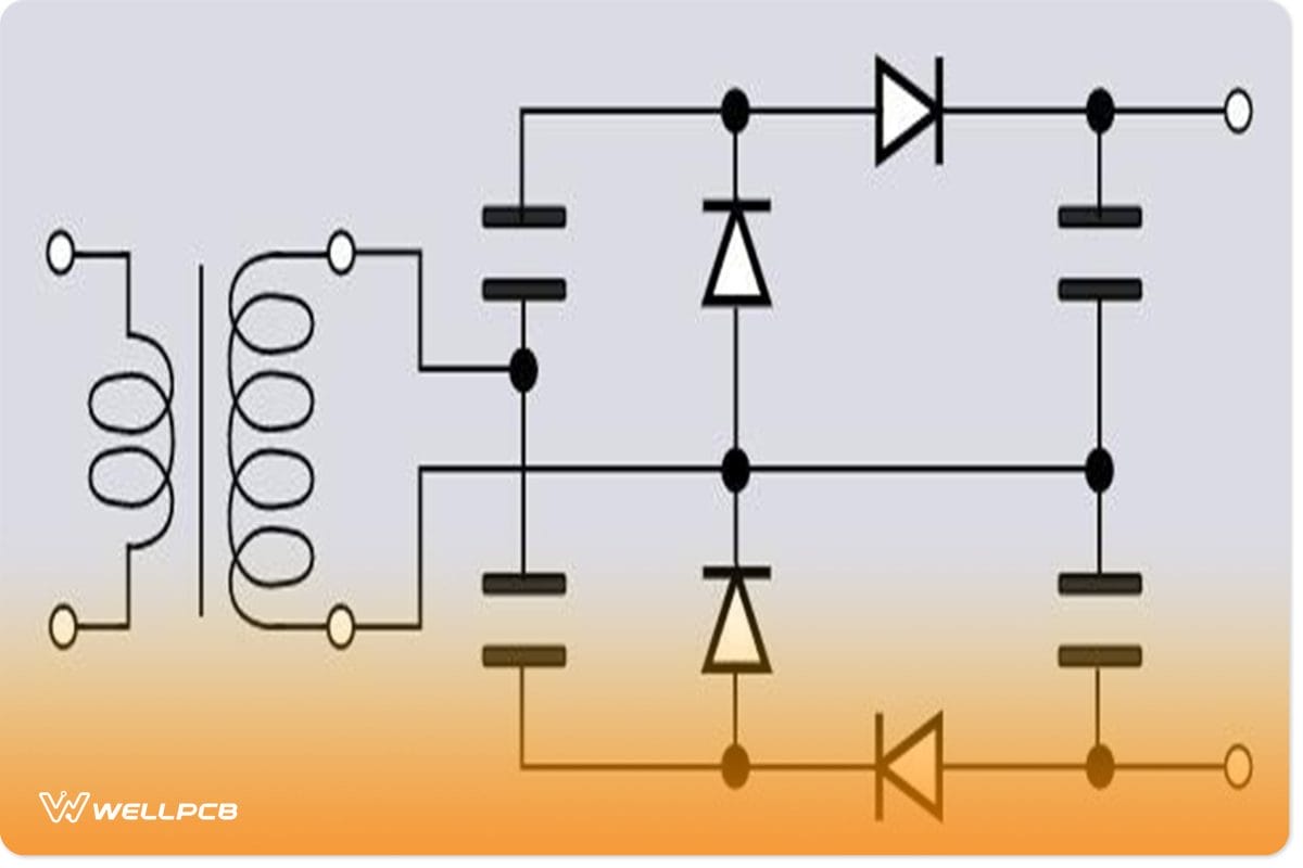
Full Wave Voltage Doubler
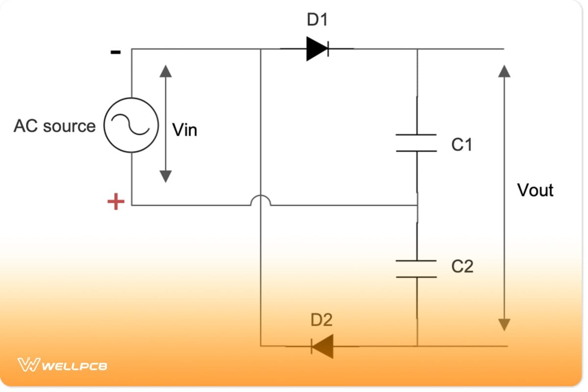
When dealing with a full-wave doubler, we measure the voltage across both capacitors C1 and C2. During the positive cycle, Vin forward biases D1, but reverse biases D2.

Full-wave DC voltage doubler circuit polarity during the positive half-cycle
During this period, there is no resistance across D1, so it short circuits and charges capacitor C1. However, D2 acts as an open circuit due to its high resistance. Therefore, C2 does not get charged.
Using Kirchhoff’s law,
Vm – Vc1 = 0
Therefore, Vc1 = Vm
In the negative half cycle, D1 gets reverse biased, but the polarity forward biases D2.
Full-wave DC voltage doubler circuit polarity during the negative half-cycle
Applying Kirchhoff’s law,
-Vm + Vc2 = 0
So Vc2 = Vm
Remember, C1 got charged in the previous cycle, so both are at the peak voltage Vm. Therefore, if you connect a load across both capacitors, you will get 2Vm.
What is the Difference?
If you look at the equations, they are somewhat similar, so what is the difference between a half-wave and full-wave voltage doubler?
The former charges capacitor C1 during the first cycle and then discharges it during the second cycle. It creates the problem of producing a ripple voltage equal to the supply frequency, making it difficult to smooth out the ripple frequency. Therefore, the output voltage curve is not very smooth.
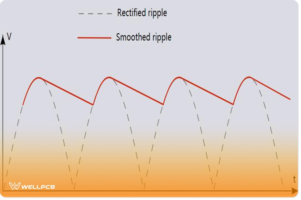
Ripple voltage diagram before and after smoothing
However, a full-wave voltage doubler acts more like two half-wave rectifiers. Therefore, the output voltage curve is smoother.
It is worth noting that with both half-wave and full-wave circuits, we have to assume that the capacitors C1 and C2 have no charge initially.
Applications of Voltage Doubler
- Ion pumps
- Television CRT
- X-Ray systems
- Copy machine
- Radar equipment
- Traveling wave tubes
- Microwave ovens
- Bug zappers
Summary
In conclusion, voltage doublers are vital circuits in many devices because they are cheap to make and do not weigh as much as transformers.
That said, the transformer-rectifier circuits produce much smoother DC output voltage curves, but considering the pros and cons for each, voltage doublers have the advantage.
Additionally, you can add filter circuits to the doubler to smoothen out the output to match a transformer-rectifier combination.
If you need the components to make these circuits, contact us to get them at unbeatable and affordable prices.