
Voltage monitors are necessary for checking the voltage level in different circuits. They work by comparing an analog voltage signal with another or with a reference voltage to determine which voltage is greater. Voltage monitoring circuits are beneficial in various products, and you can even use a voltage comparator in a personal project. Therefore, this article aims to use different examples to better your understanding of voltage monitoring circuits.
Contents
1. The LM339 in a Battery Voltage Monitoring Circuit
The LM339 voltage comparator IC is a 14 pin op-amp that can run at its maximum gain. Since it is a low voltage IC, it can monitor voltages from batteries and help detect problems in real-time.
To examine how it works in a battery voltage monitor circuit, you need:
- 2, 1K Resistors
- 1N5233 Zener Diode 6V
- 5K Potentiometer
- Buzzer
- LM339 Comparator circuit
- 1 LED
- 9V Battery
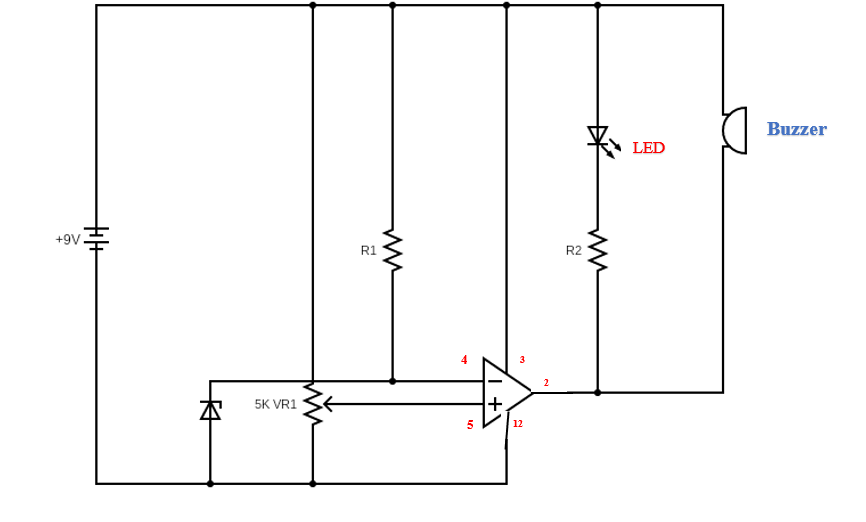
LM339 in a battery voltage monitor circuit
In this circuit, the voltage will flow through the potentiometer to the IC through its non-inverting terminal, i.e., pin 5.
Then, the resistor (R1) limits current flow to the Zener diode through pin 4, the inverting terminal.
Remember, the Zener diode contains the reference voltage, and the IC will compare incoming voltages to determine its output voltage.
The IC determines its output voltage by comparing the initial(V1) and secondary(V2) voltages. Therefore, if V1>V2, the IC will output a Vcc signal; however, if V1<V2, then there will be a GND.
To reiterate, if the initial voltage exceeds 6V, then the comparator output will be in a high state. Therefore, the buzzer and LED indicators will not indicate because their terminals will be connecting to only a positive voltage.
However, when the incoming voltage is below 6V, the buzzer will sound, and LED will light.
Also, the resistor’s (R2) job is to regulate the voltage going to the buzzer indicator. You can use the potentiometer to adjust circuit voltage levels and sensitivity.
2. Using the LM324 IC in a 4 LED Monitoring Circuit
The LM324 is appropriate for this circuit because it is one package of quad amps. It can also withstand higher voltages than other comparators.
To facilitate the circuit, you need:
- Resistors
- 10K Potentiometer
- Zener diode (3.3V)
- 4 LEDs
- 10K Presets
- LM324 IC (A1 to A4)

The LM324 is a 4 LED Monitoring Circuit
All the op-amp inverting pins connect to a specific voltage from the Zener diode in this circuit. The resistors determine which voltage goes to which op-amp.
Also, the op amp’s non-inverting pins act as sensors and terminate at the variable resistors.
To adjust the voltage thresholds, ensure the slider arm faces the ground terminal so that non-inverting pins have 0 potential.
Then, use a regulated power supply to apply the lowest level voltage as the initial power supply. While at it, adjust P1 until the white LED lights up.
Next, apply the second voltage level you wish to monitor and adjust P2 until the yellow LED indicates. Follow the same procedure for the P3, and P4 presets and seal all of them when done.
The above setup will put the circuit in dot mode. You can change it to bar graph mode by disconnecting all LED cathodes and linking them to GROUND.
Comparing the battery voltage and reference voltage from each comparator output generates the circuit’s output voltage.
Reference voltage originates from the Zener diode that connects to the bias resistor R1.
A 5-6 voltage is suitable because Zener diodes have the highest thermal stability in these ranges.
Note that all LED cathodes should connect to the GROUND line.

3. The LM3915 in a Voltage Regulating Circuit
The circuit is a ten-step function that lets you determine your battery’s exact voltage level while charging.
Power supply voltages in this circuit can range from 1 to 35V, and in our circuit, we will use a 12V battery.
For this circuit, you will need:
- 10 LEDs
- LM3915 IC
- A transistor
- 3V constant voltage Zener diode
- Resistors
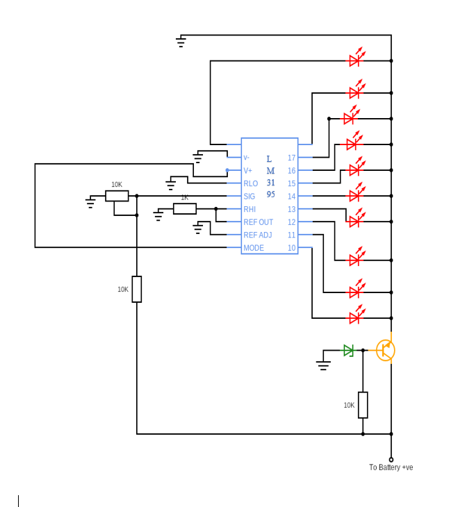
LM3195 is a 1O Step regulating circuit
In this circuit, the transistor is an emitter follower distributing a high current, and the Zener diode distributes a constant 3V.
The setup is necessary to prevent the LEDs from draining excessive current from the voltage rails and, in turn, overheating the IC.
Voltage also gets into the IC via pin 5 after going through a voltage divider consisting of the 10K resistor and preset.
The LEDs on the output ends of the IC produce the necessary indications.
To calibrate the LED voltage monitor circuit, divide the total input voltage by 10. That way, you can determine the suitable input rate to light the LED indicators.
For instance, if the full-charge voltage level is 12V, you will increase the input voltage by 1.2V until all the LEDs eventually light.
4. A Car Battery Voltage Monitor Circuit
The strategy above is also applicable in making a car battery voltage monitoring circuit. To do this, you will need:
- 3.3V Zener diode
- LEDs
- Resistors
- LM324 IC
- Buzzer
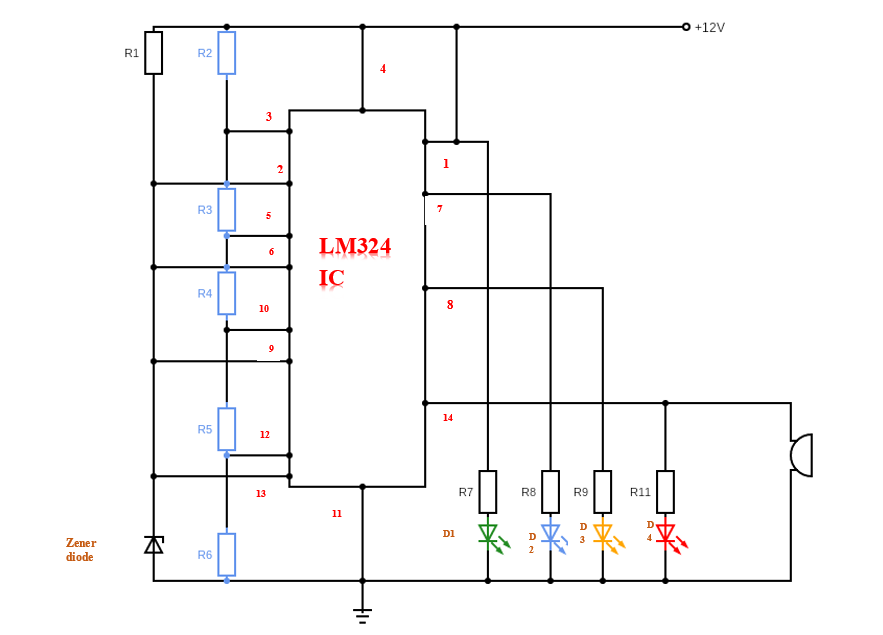
A Car battery voltage monitoring circuit with the LM324
In the circuit, the Zener diode voltage can range between 3.3V but should not exceed 6V. The R2 to R6 resistors regulate the voltage to the non-inverting terminals of the LM324.
You can use either 1K presets or fixed resistors for the LED battery voltage monitor.
The LEDs will indicate depending on the AC voltage level from the IC’s non-inverting terminals. Hence a high voltage on the comparators’ output will influence corresponding LEDs to indicate.
For instance, in our circuit, the LEDs light with the following conditions:
- The first indicator will light with an 11V battery
- The first and second will glow with a 12V battery
- The first, second and third will indicate with 13V battery
- All LEDs will indicate with a 14V battery.
Here is a video of further LM324 IC applications.
Conclusion
Hopefully, you now understand how monitor voltage circuits work in different settings. The various monitors help simplify energy monitoring, and your choice of IC will impact energy costs. Therefore, consider choosing a suitable IC that can match your needs and constitute an effective device. You may also reach us for any queries, concerns, or compliments.


