Continuous technological advancement in signal transfer, whether electrical or optical, necessitates better signal sensing devices. Therefore, voltage sensors fall in this category.
They’re small, lightweight, high accuracy, and eco-friendly devices that come in handy when monitoring electrical circuits. Therefore, suitable voltage sensors should be sensitive to parameters under measurement, insensitive to surroundings, and not tamper with the parameters.
In today’s article, we’ll learn about voltage sensors, their working, types, and applications.
Contents
What is a Voltage Sensor?
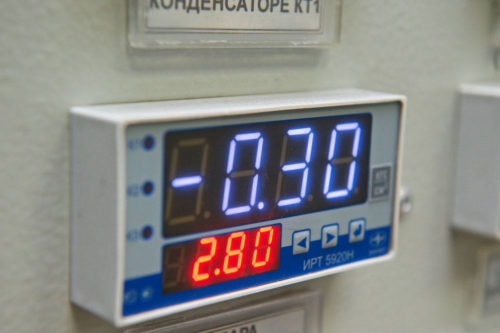
Fig 1: Steam Pressure and Electrical Voltage Sensors in the Central Control Point of a Heating Plant
A voltage sensor is a wireless sensing device for detecting, measuring, and communicating the voltage in devices. Also, it can detect the level of an optical signal in circuits (an optical voltage sensor) and respond accordingly.
Voltage sensors have voltage as their input signals, while the output signal varies with its design. Therefore, outputs can be analog voltage signals, switches, current signals, or audible signals.
Furthermore, it’s helpful to maintenance teams to detect the presence and levels of both DC and AC voltages in circuits. Also, they provide continuous monitoring of courses to detect any voltage changes that may indicate the presence of a fault.
The adoption of voltage sensor technology is responsible for improving conventional voltage measuring methods.
Types of Voltage Sensors
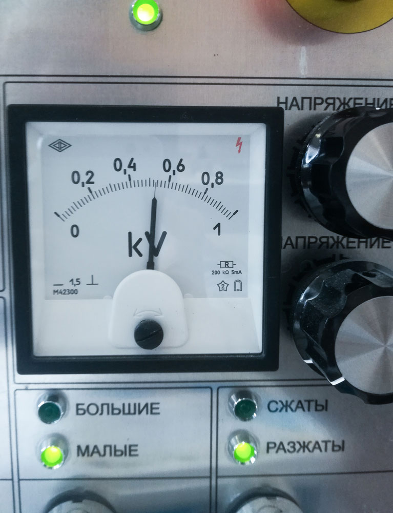
Fig 2: White Voltage Sensor on an Instrumentation Panel
AC Sensors
AC voltage sensors are helpful in electrical installations and automatic control in power and telecommunications electrical systems. We can broadly group them into three-phase and single-phase voltage sensors or transducers.
Furthermore, their typical applications include load sensing, power loss detection, and power demand control. Additionally, you can use AC sensors for safety switching and controlling cases of motor overloads.
DC Sensors
From the naming, DC voltage sensors detect and monitor DC voltages in electrical systems.
They’re helpful in instrumentation, automation systems, fault detection, temperature control, and power isolation and control.
Additionally, other applications include remote DC monitoring and energy control in control systems.
Specialized Sensors
Specialized voltage sensors are voltage sensors that serve specific purposes or niche applications in electrical systems. They assist in application-specific control systems and may be part of a feedback control loop in electromechanical systems.
Examples include specialized capacitive sensors, special air quality sensors, automotive sensors, and specialized pressure sensors.
Resistive Type Sensors
Resistive type sensors comprise a bridge and voltage divider circuits.
A bridge circuit is more effective than a series resistance voltage divider as it only amplifies the sensor’s resistance change.
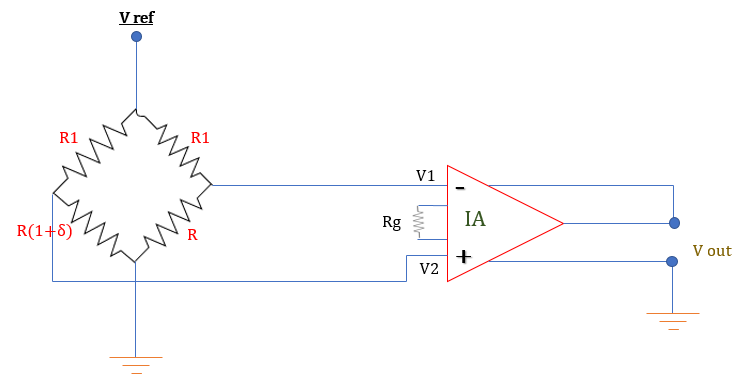
Fig 3: Circuit Diagram of a Resistance Bridge Resistive Voltage Sensor
We calculate the output voltage using the equation below.

Where,
- A is the gain of instrumentation amplifier
- δ is the change in the sensor’s resistance
Remember to set the gain high since you’re amplifying a voltage change resulting from a change in the sensor’s resistance.
Capacitor Type Sensor
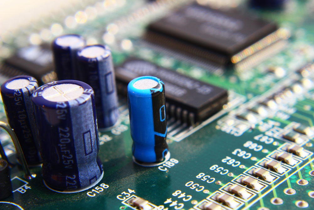
Fig 4: Capacitors on a Printed Circuit Board
Unlike its resistive sensor counterpart, a capacitor-type sensor uses two capacitors for capacitive coupling. Therefore, to understand capacitive coupling, let’s look at the working of a capacitor.
A capacitor has a non-conducting material (dielectric) between two conducting plates. If we pass an AC voltage through the capacitor, an AC will flow through the dielectric.
The current flows through due to alternate repulsion or attraction of electrons by the opposite plates. Therefore, the flow of charge carriers through the dielectric completes the circuit without a hardware connection between the plates.
We shall look at voltage division between the two capacitors in series.
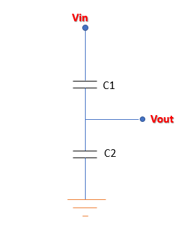
Fig 5: Circuit Diagram of a Capacitive Voltage Sensor
Remember from Ohm’s Law that the most significant voltage develops across the capacitor with the largest impedance in series capacitors.

- Xc → Capacitive reactance (Ω)
- f → Frequency (Hertz)
And the smaller the capacitor, the bigger the capacitive impedance.
For a capacitor-type sensor, the smaller capacitor is at the sensing tip. Therefore, you place the tip (a high impedance point) into a live series capacitive circuit when detecting a voltage.
A large voltage develops across the sensing circuit, and a buzzer or light goes on.
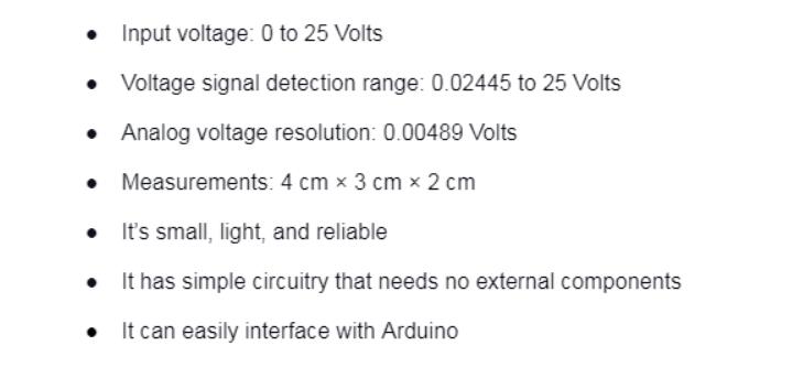
Voltage Sensor Module Features & Specifications

Voltage Sensor Working Principle
A voltage sensor module is a voltage monitoring device with an input voltage range of 0 to 25 Volts. Additionally, it utilizes a resistive voltage divider circuit to minimize the input voltage by a factor of 5.
It then produces an analog signal or voltage output corresponding to the input signal’s step-down factor. In most cases, its circuitry is diminutive and can detect Undervoltage and overvoltage faults in electrical systems.
The voltage circuit consists of a voltage divider circuit of two series resistors. Therefore, when applying an input voltage, voltage division occurs between the two resistances.
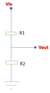
Fig 6: Circuit Diagram of a Resistive Voltage Divider
The following equation takes an output signal voltage from the second resistor.
The output voltage is directly proportional to the input voltage and the ratio of the series resistances.

Advantage of Voltage Sensors
Voltage Sensor Applications
Below are the significant applications of voltage sensors
AC Voltage Sensors
Controlling power demand、Fault detection、Motor overload control、In safety switching applications、Load sensing
DC Voltage Sensors
Data acquisition、Building control systems (BCS)、Temperature control、Energy、management control systems (EMCS)、Fault detection、Power demand control
Conclusion
In conclusion, voltage sensors are very crucial components of electrical circuitry. They’re critical in high power circuitry and small PCBs found in our home electronics.
Contact us if you want to know more about voltage sensors, their accessories, or need to order components.


