
If you own a fish pond or a swimming pool, you understand how a water leak can be frustrating. It’ll prompt you to keep refilling the water, which is tedious, time-consuming, and expensive in the long run. Hence, keeping track of whether there is a slow damaging leak is highly significant. But you don’t need sophisticated water leak detection systems to know when there’s a problem. A simple water detector circuit will prove handy in identifying a plumbing leak with much hassle. We are going to discuss the dynamics of this simple project at length. Take a look.
Contents
Water Detector Circuit Schematic
Below is a schematic representation of this circuit. Circuit diagrams may differ, but the basic representation is illustrated below.
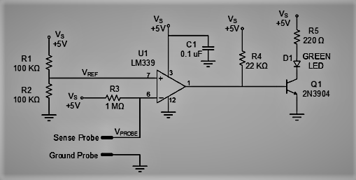
Figure 1: A Water Detector Circuit Schematic
Note: The circuit illustrated above will use an LM339 comparator to compare sense probe voltage and the reference voltage VREF. We assume that you require the circuit to check the changes in the water level in a swimming pool or pond.
Thus, in practical terms, you will require a sense probe and a ground probe, as shown in the illustration below.
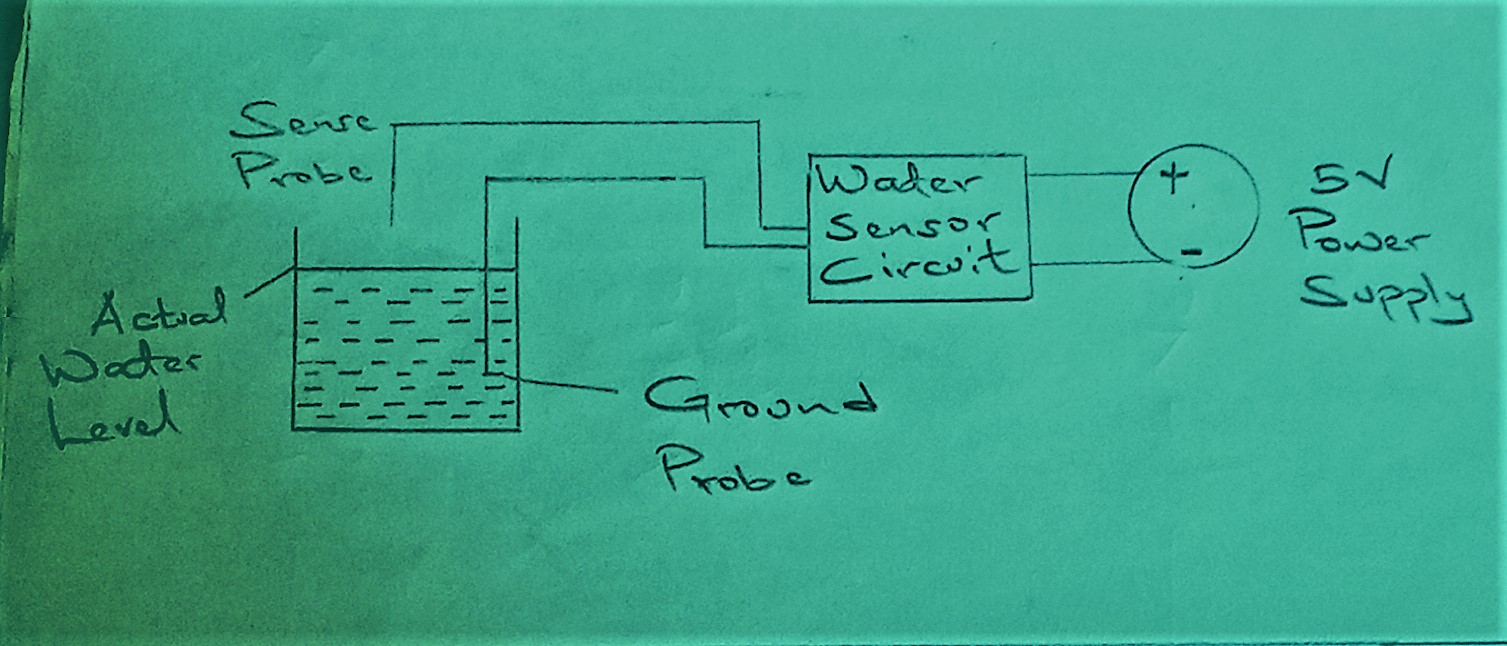
Figure 2: Water Detector Setup illustration
The probes, in this case, are breadboard jumper wires.
Water Detector Circuit Components
From the above schematic, you can identify several electronic components. They include:
R1 to R5- ohm resistors
Q1- 2N3904 Transistor
C1, = 0.1 uF capacitor
Diode D1/ Green LED
T1= BC557 PNP transistor
U1- LM339 Comparator IC
How does the Circuit Work?

Figure 3: A Technician Working on a Circuit
As we earlier mentioned and illustrated in the circuits in the figure, the LM339 comparator is very important. Also noteworthy is a voltage probe that we earlier introduced as the sense probe.
Now the voltage at this probe will be primarily dependent on whether it’s in contact with water or not.
In an open circuit, the sense probe is not in contact with water. Hence, as represented in the above schematic, the voltage at the sense probe will be 5V.
At this instance, the comparator’s input impedance is very high. Consequently, a tiny current will flow through R3. Also, there will be zero voltage across this resistor. Therefore, the comparator inverting input voltage and the sense probe voltage will be 5V.
Voltage Divider
Next, make contact between the sense probe and water. There’ll be resistance between the ground and the sense probe at this instance. Subsequently, the resistance will form a voltage divider between sense voltage and the ground voltage.
We are going to refer to this resistance as WATER.
Here is a representation of how you realize water resistance when the probe touches water.

Figure 4: Water Resistance Illustration
The circuit equations for the voltage at the sensor probe VPROBE are:

When RWATER is lesser than 1 MΩ, the voltage at the VPROBE will be under 2.5V. We assume that water has a resistance measuring less than 1 MΩ since we are not testing purified water.
In this case, the resistivity of pure water is higher than that of unpurified water.
Hence, it’s possible to determine if the sense probe is in contact with water by checking its voltage levels. If it’s above 2.5V, the probe is not in contact with water. On the other hand, if it is below the 2.5V threshold, there’s every chance it’s in contact with water.
Remember, the voltage comparisons here are possible since we have a comparator. Also noteworthy is that the reference voltage we are dealing with is due to the two 100 KΩ resistors. In this case, the resistors R1 and R2 are responsible.
How do they facilitate this process? Note, the tiny current is flowing into the comparator’s high-impedance non-inverting input. Thus, the two resistors will create a voltage divider that yields a voltage of 2.5V reference voltage.
Figure 5: A Pool Expert conducting Routine Maintenance Practices
Comparators
Also noteworthy is that the LM339 has four comparators. In this circuit, only one of the comparators is necessary. Another significant feature of the LM339 comparators is that they have open-collector outputs.
Hence, when the VPROBE is less than the reference voltage, the comparator makes its output floating. Conversely, the comparator will connect its output to the ground when the sense probe voltage exceeds the reference voltage.
Another significant component of this basic water detector circuit is the transistor Q1. Earlier, we’ve mentioned that in scenarios when VPROBE > VREF, the comparator’s output will connect to the ground. Consequently, there’ll be no base current via Q1.
Hence, the transistor will be in a cutoff state. Resultantly, no current will pass through the LED when water is off the sense probe. The reverse process occurs when VPROBE < VREF, t
The role of R4 in this circuit prototype is to saturate the transistor, consequently switching on the LED detector. It will happen when the sense probe is in contact with water.

How to Test the Circuit?

Figure 6: A Green LED Button
After connecting the circuit, as we have highlighted above, it’s now time to test it. First, set the ground probe in water and the sense probe not in contact with water. You will notice that the green LED will remain off during this setup.
Next, place the sense probe on the water surface as the ground probe remains in the water. The green LED will go on.
By these two simple tests, you can determine if the circuit is operational or not. Note that we have used breadboard wires as the probes in this circuit. They are suitable for a simple moisture sensor circuit.
For a sophisticated project, it’s imperative to check out if your probe materials will withstand corrosion. Also, you’ll need an upgrade on these basic components to improve detection reliability.
Is There an Alternative Circuit?

Figure 7: An Electrician Assembling a Circuit
There is an alternative circuit to what we have just discussed above. The only difference about the alternative is that you’ll have to swap the comparator’s inputs. However, only a few adjustments feature in the alternative circuit as the electricity concepts are similar.
Conclusion
Maintaining a constant water level is essential in numerous applications. We have just elaborated on achieving that process using a primary water detector circuit.
You can try it out as your college project to see if what we’ve just explained works. Also, feel free to engage us as you tackle the project by reaching out. We will afford you all the help that you require.


