Think of a scenario where you want to obtain the flow rate of a coffee machine or water pipe. Such measurement is possible when you’ve got a flow rate pulse sensor. Today, we’ll elaborate on the working of a YF-S201 flow sensor and its applications.
Contents
What is YF-S201?

Fig 1: A water flow measurement sensor
It’s a water flow measurement sensor comprising a hall-effect sensor, water rotor, and plastic body valve.
To determine the liters per minute, the water flow sensor YF-S201 records the hall sensor’s pulse output. On average, a pulse equals 2.25 milliliters, but this device is not a precision sensor. Thus, professional calibration is necessary to improve its accuracy.
YF-S201 Pinout
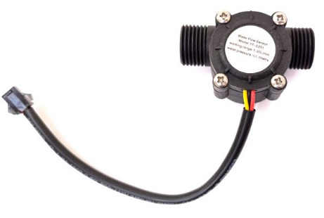
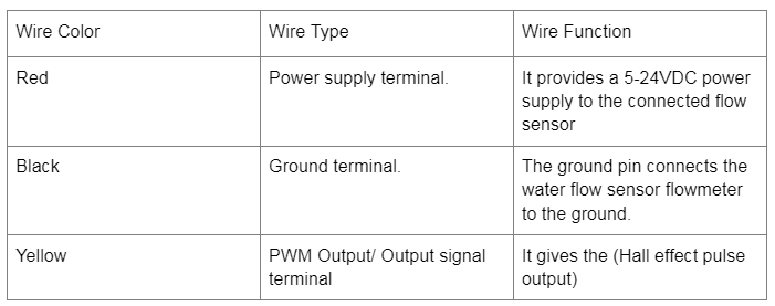
Fig 2: A Water flow Sensor has three main terminals (RED, BLACK, YELLOW).
This flow sensor type has three wires colored red, black, and yellow, as highlighted in the table below.
YF-S201 Features
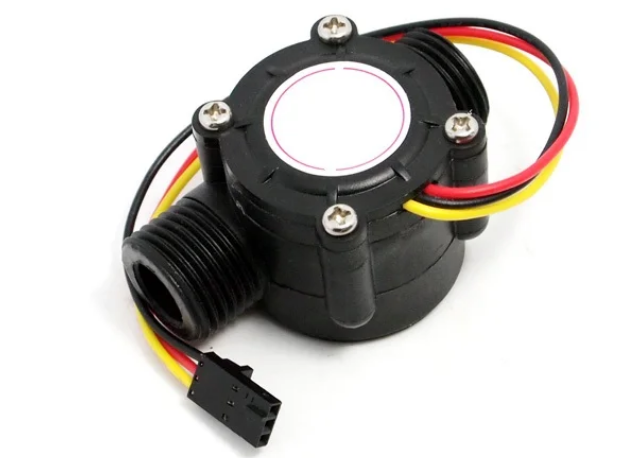
Fig 3: A Hall Effect Sensor
The hall effect sensor’s properties are as follows:
- It has a 5 to 18V DC working voltage and can draw a maximum current of 15mA at 5V
- Also, the 1-30L/Min Flow sensor features a 5V TTL output and a working temperature range of -25℃ to +80℃.
- Thirdly, it operates best at a humidity of between 35% to 80% Relative humidity, and its overall precision/accuracy is ±10%.
- Fourthly, the flow sensor measures liquid/water with a maximum pressure of 2.0 MPa. It also can make a maximum of 450 pulses per liter.
- It also has a 50% +-10% output duty cycle.
- Moreover, it has an output rise time and output fall time of 0.04us and 0.18us, respectively.
- Lastly, its pulse rate depends on its flow rate, sensor orientation, and liquid pressure.

Interfacing YF-S201 with Arduino
Parts Required
First, assemble the following components
- A water flow sensor,
- Arduino Uno,
- Three breadboard cables.
Essential Steps
- Assemble the above components as shown in the picture below.
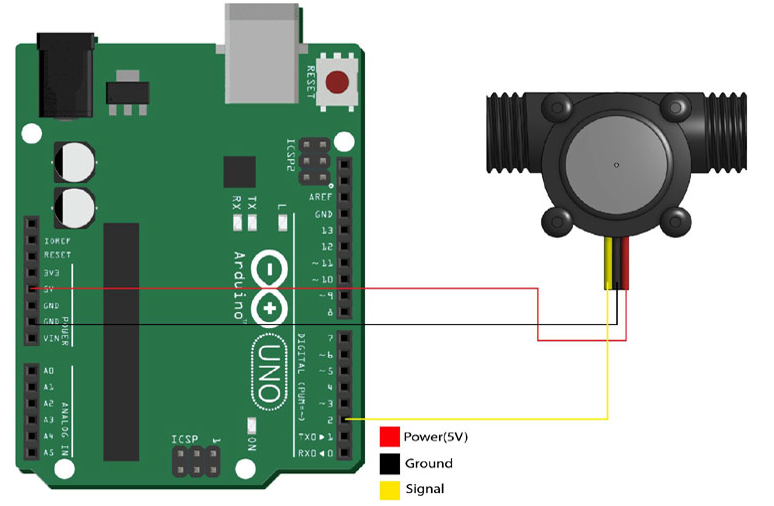
Fig 4: Arduino Uno and Water flow sensor array
- Connect the sensor’s red cable to the microcontroller’s 5V terminal and the yellow cable to the Arduino’s digital pin. Lastly, as the diagram illustrates, connect the black cable to the Arduino board’s GND.
- Next, run the code below on your Arduino board.
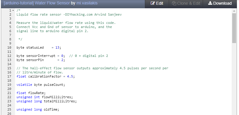
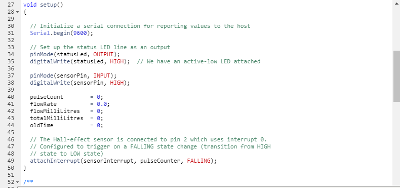
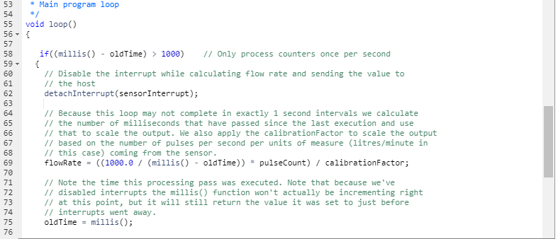
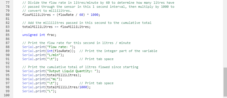
- You’re also free to modify the code by clicking the ‘Edit’ button and inserting the parts you deem necessary but are missing.
- Click the serial monitor button to initiate serial communication. Your sensor is now ready for use, and you can connect it with water to test the rate of flow.
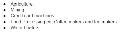
Applications of YF-S201
It’s helpful, especially in rate of water flow measurements, such as in water vending machines. Still, it finds further use in the following areas:
Conclusion
If you want to obtain the rate in litres of water flowing through a pipe, consider this component. For additional instructions on how to use your water flow sensor, check out your model’s user manual. Finally, write to WellPCB for any query, and we’ll always be at your service.


