
How do power control systems withstand high inrush currents? It seems like an arduous task. Nonetheless, this is where zero-crossing detectors (ZCD) come in handy.
With zero-crossing detection, the transition of a signal waveform will happen seamlessly. Therefore, a crossing detector circuit is important for systems requiring a time interval.
We’ll elaborate on how zero-crossing detectors operate. Also, we’ll explain simple methods of creating a crossing detector circuit. Thus, read on for insights.
Contents
1. Zero-Crossing Detectors Principle
A zero-crossing detector operates in a circuit network of electric power control systems. It facilitates the conversion of a comparator output waveform. It happens when an AC Signal attains zero reference voltage. Consequently, the device delays in time. The aim is to protect the circuit from high input signal currents.
2. Basic Zero-Crossing Detectors Circuit Description
First, here is an illustration of a zero-crossing detector circuit.
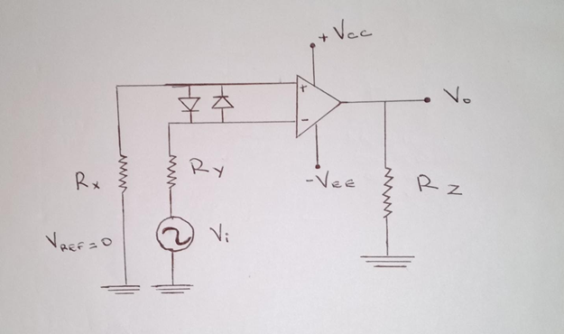
Figure 1: A Circuit Diagram Illustration of a Zero-crossing Detector.
The above series circuit illustration shows a simple crossing detector circuit. During assembly, connect the input signal to the operational amplifier’s inverting terminal. For the non-inverting terminal, ground it via input resistors.
The device identifies when the input signal is different from the reference voltage. You should set the reference voltage at 0. Therefore, every time this happens, the output signals saturation level will shift.
Figure 2: A Circuit Board
Apply an input signal at the non-inverting terminal of the operational amplifier. At this instance, the voltage reference level is at zero. The system will compare the sine wave at the op-amp’s input with the voltage reference.
Every instance, the sine wave’s phase will shift from negative to positive and vice versa.
Let’s consider each probable scenario of the input signal.
Take, for instance, a case when there is a positive sinusoidal signal at the input. The comparator will compare the input signal against the reference voltage level. Therefore, the equation of this scenario is:
V Output = VReference – VInput Signal
Hence, given that you have 0V reference voltage, we can equate VReference to zero. Thus, the equation will change to:
V Output = 0 – VInput Signal
Consequently, the voltage of the output waveform signal will have a negative saturation. Check this final equation:
V Output = – VInput Signal
Therefore, a positive pulse yields a negative output waveform.
On the other hand, consider a scenario when there is a negative sinusoidal signal. Again, the comparator will compare the input signal to the reference voltage level.
Hence, the equation will again be V Output = VReference –VInput Signal.
When we replace the = VReference in the equation with zero, we’ll obtain,
V Output = 0 – (VInput Signal)
Thus, V Output = + VInput Signal
The output waveform signal will have a positive saturation in this case.
Therefore, the zero-crossing detector efficiently converts the input signal to the output waveform of the opposite sign. If the input signal is negative, the crossing circuit converts it to positive and vice versa.
3.How to Make a Zero-crossing Detector Circuit?
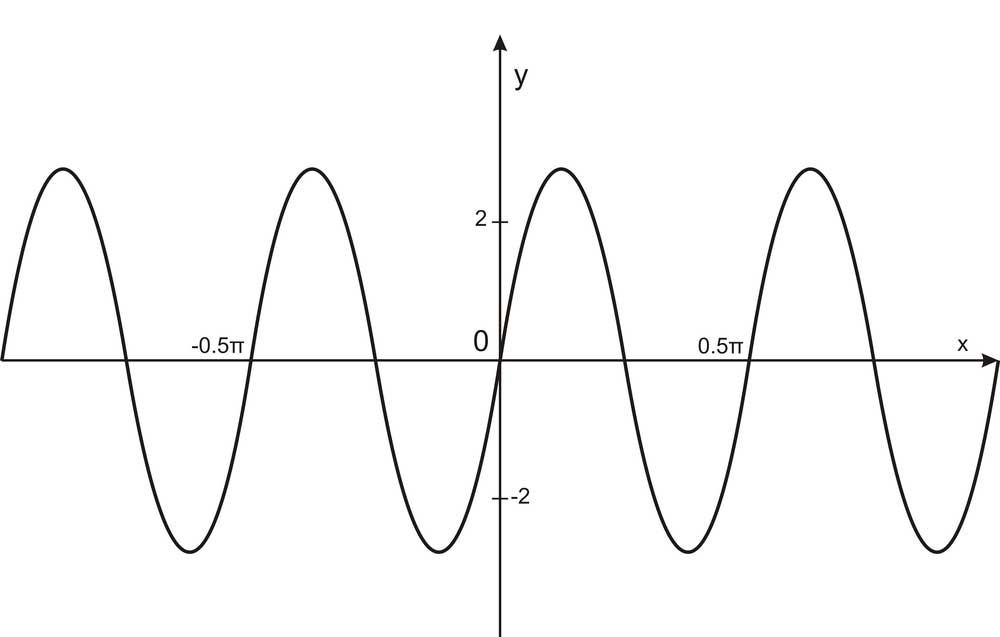
Figure 3: Sine Waves
You can easily design a zero-crossing detector. Also, you can use this circuit for a wide range of applications.
Here are the components that you need for this circuit:
A 6V Zener Diode
Two 100K Resistors
IC 741 Comparator
You must ensure that you connect the input AC from a bridge rectifier. Also, in this circuit, the IC 741 operates as a comparator. You should provide a supply voltage of 12V.
Also, ensure that you connect the non-inverting pin to a 1N4148 diode. On the other hand, you should connect the inverting pin to the input signal of choice.
Note that the output waveform of your circuit will be the reverse of the input signal. Thus, the circuit follows the conventional zero-crossing detectors’ principles.
When there is a positive current at the input pin, the device will detect this. The change of the output waveform will happen when the voltage reference is at zero. The opposite will happen when you connect an opposing current. In this case, the output will be positive.

4. Applications of Zero-crossing Detector
There is a wide range of applications of zero-crossing detector circuits. You’ll find them in an electronic device such as a frequency counter. Additionally, you’ll also find them in power electronic circuits.

Figure 4: A 3D Illustration of Electronic Components
Here are some of the typical applications of a crossing circuit:
ZCD as Phasemeter
When you have two voltages, you can use a ZCD as a phase meter to determine the phase angle. The ZCD will first obtain sequential pulses in the positive and negative cycles. Then, it will measure the voltage of the time interval of the first sine wave voltage pulse. It will repeat the process for the other sine wave’s voltage pulse.
Thus, the interval of time will give the phase difference between the input signal voltages. You can use the phase meter for sine waves of zero degrees to 360 degrees.
ZCD as Time Marker Generator
Consider the comparator circuit diagram of a zero-crossing detector in Figure 1. If the input pin is a sine wave, the output signal will be a square wave generator. Thus, it will create a series circuit.
Also, consider a scenario when the time constant is relatively small to the period. In such an instance, the voltage at the resistors can be a positive pulse. Also, it can be a negative pulse. Apply a voltage to a clipper circuit via a diode. It yields load voltage with positive pulses only. Hence, you will have a conversion of a zero-crossing detector’s sine wave to positive pulses. The prerequisite of this result is a network circuit and a clipper circuit.
Zero-Crossing Detector Using IC 311 and Transistor
Figure 5: Wave Graphics
You can also use a zero-crossing detector in the design of an Op-Amp comparator circuit. We have illustrated this direct application in Figure 1. When you use it in this manner, it will be a square wave converter.
Also, in this circuit, you can use either the inverting or non-inverting comparator as a zero-crossing detector. Nonetheless, you must ensure that you set the reference voltage to zero.
The working principle of this circuit is also similar to the other zero-crossing detector applications.
Thus, when positive input voltage crosses zero, the output waveform will be in negative saturation. On the other hand, when the input voltage is negative, the output waveform will be in positive saturation.
Therefore, negative cycles in the wave input will yield positive waveforms. Similarly, positive cycles in the wave input will produce negative waveforms.
Zero-crossing Detector Using Optocoupler
Another way of using a zero-crossing detector is in the design process of an optocoupler. Here is an illustration of an analog design optocoupler.

Figure 6: An Optocoupler Illustration
Looking at an output waveform of the circuit, it changes depending on the input. For instance, when the input signal reaches 0, the output waveform will rise. It occurs every time the input signal comes to this point, as illustrated in the above examples.
Conclusion
In a nutshell, zero-crossing detectors are essential in power control systems. Without them, it would be possible to operate AC cycle circuits.
We have other insights about other types of circuits. Check out our site for more information on circuits. Also, don’t hesitate to contact us in case of any queries.


