Contents
What is a 9V Voltage Regulator?
A 9v voltage regulator can either work by stepping up or down a power supply. Consequently, this property makes the device an essential unit in projects since it can convert higher and lower input voltages. Also, the device works by efficiently producing a 9v output voltage from a power supply voltage of between 3v-30v. Thereby allowing a typical output current of 2A when the input voltage is close to the output voltage.
When you connect the regulator correctly in your electronic circuits, it should offer typical efficiencies of about 80% to 90%.
Moreover, this regulator’s flexibility in input voltage is perfect for battery-powered applications. This feature is because the battery voltage starts above the required output but eventually drops below. Also, the whole process happens as the battery discharges.
However, you might need new batteries and form factors without the typical restriction on the current draw remaining over the required voltage throughout.
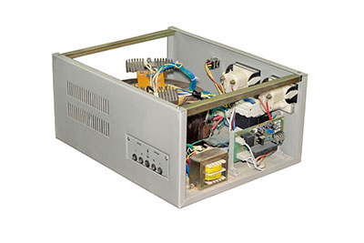
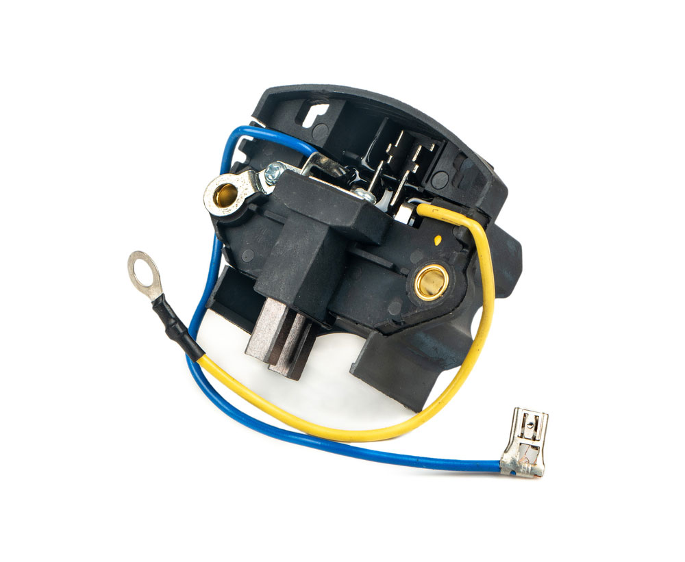
(a voltage regulator.)
Pin Configuration
A 9V voltage regulator has to work with an integrated circuit to achieve good results. For example, an L7809 voltage regulator IC has 3 pins. These pins include the IN, GND, and OUT pins. Each pin has been described below.
| Pin no. | Pin name | Description |
| 1 | IN | This pin receives the positive voltage from the battery voltage. |
| 2 | GND | GND pin earth the circuit or acts as the ground terminal. Also, this pin is common to both the input pin and output pin. |
| 3 | OUT | This pin of the IC takes out the output regulated 9v from the system. |
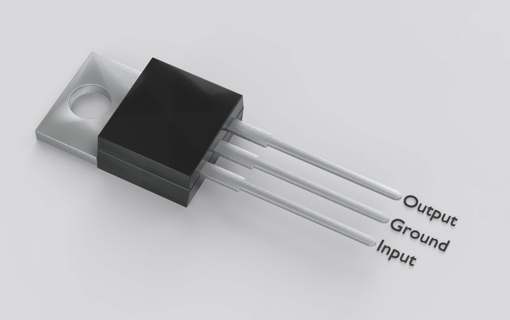
(an electronic package with a similar pin configuration)
Characteristics of the 9v Voltage Regulator
- Firstly, this linear voltage regulator has a fixed output voltage of 9v with an accuracy percentage of about 4%.
- Secondly, the regulator offers a wide range of efficiency(80% -90%) depending on the load quiescent, output and input voltages.
- Also, the regulator offers an integrated reverse-voltage protection circuit of up to 30v.
- Moreover, this regulator can offer over-temperature shutoff, over-current protection, and under-voltage shutoff.
- The 9v voltage regulator has four 0.086* holes for M2 screws.
- Lastly, the device offers several options to consider your connections. This feature has 0.1*-Spaced smaller holes for header pins and larger holes for terminal blocks.
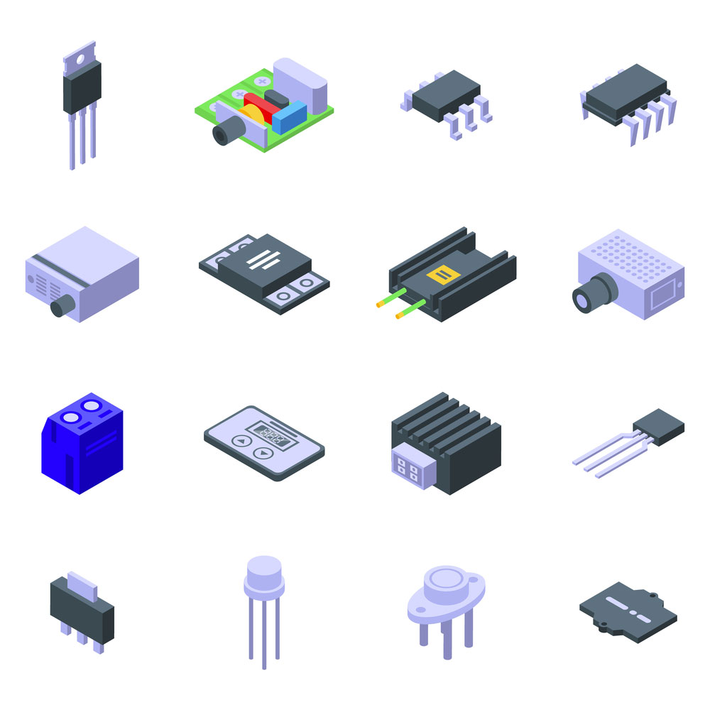
(voltage regulator icons.)

How to use a 9v Voltage Regulator?
To achieve a proper output voltage using a 9v voltage regulator, you need to use an L78S09 regulator IC. Importantly, the integrated circuit is vital because it provides local-on-card regulation. Also, this feature helps to eliminate the distribution of problems brought about by the single-point regulation.
The L78S09 IC is indestructible because it sets an internal current limiting thermal shutdown. In addition, the integrated circuit offers safe area protection. Moreover, if you have an adequate heat sink, the IC gives out over 2A of maximum output current.
Initially, the design of the L78S09 IC was for fixed voltage regulators. However, it can also work with other external components to adjust voltage and currents.
Here are the few materials you will require to achieve a good electrical connection.
| Serial no. | Electrical component | Quantity |
| 1 | 1N5400 diode | 1 |
| 2 | Heat sink | 1 |
| 3 | Capacitor(220uf.47uf) | 1,1 |
| 4 | L78S09 IC | 1 |
| 5 | Connecting wires | 1 |
| 6 | 12-35v DC supply unit | 1 |
| 7 | Breadboard | 1 |
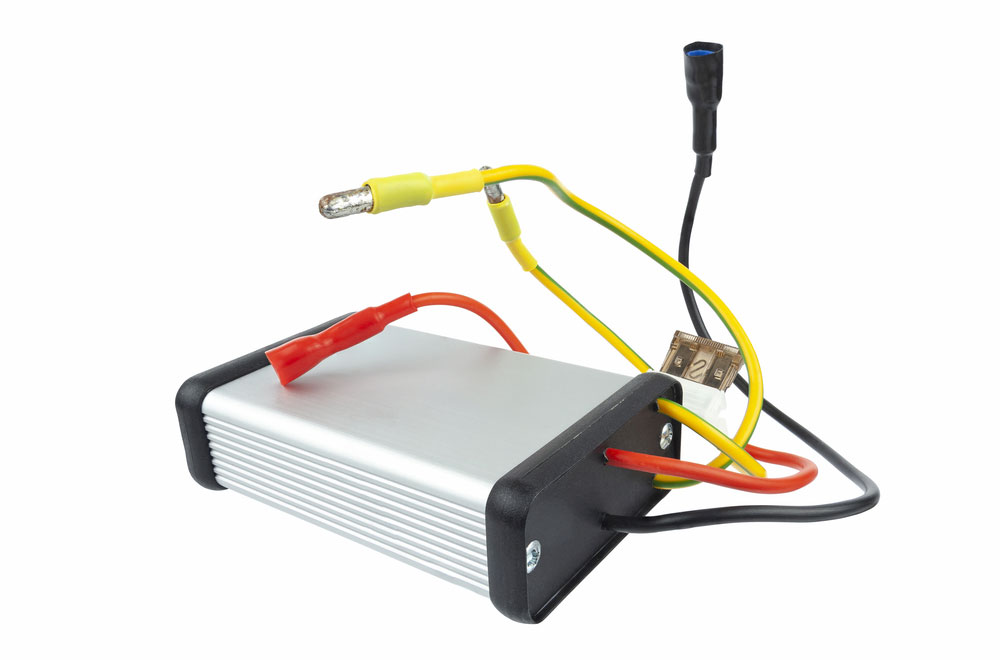
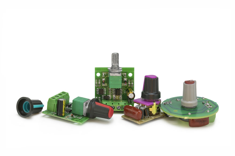
(relay generator voltage regulator.)
Circuit description
This circuit is a simple one. From the circuit, the L78S09 integrated circuit is the essential electrical device. It works quite similarly to the human heart. The IC receives a direct current ranging between 12-35V from the circuit current.
Notably, this particular circuit will work perfectly without any extra electrical components. However, for reverse polarity protection, you require a diode as an input.
The input capacitor with 200uf works by removing the residual noise. After, the IC can produce a 9v output. Then, this output travels to the second output capacitor of 47uf to cancel out any extra noise. After this current has undergone the entire process, it becomes clear enough to travel to the output pin.

(9v voltage regulator circuit)
How to connect?
From the diagram, directly after the battery packs, you can connect a diode that prevents current backflow. You should make sure that the diode and the IC are parallel. Also, the capacitors should be in series with the diode and IC but parallel to each other. Moreover, the device capacitors should be in series with the diode and IC but parallel.
Additionally, since the input pin powers the regulator, you can apply a voltage of up to 30v. However, the output pin has a fixed voltage of 9v that passes through it.
Also, remember the voltage pin is always on default mode. On the breadboard, you will find a 100-kilo-ohm resistor that links the enable pin to a reverse-protected input pin. Notably, a lower current below 0.6v can power up the enable pin.
As a result, the board is put into a lower space.
(adjustable voltage regulators)
Current within the resistor dominates the quiescent current drawn when in sleep mode. The current within the resistor travels to the input pin from the enable pin via the reverse voltage protection circuit. However, this process can sometimes be unnecessary. If this is the case, the enable pin is always left open or disconnected.
The enable pin, input pin, output pin, and ground pin have labels on the PCB. Also, each pin has a 0.1″ spacing between them. The spacing ensures compatibility with a solderless breadboard, connectors, and other prototyping arrangements. That uses a 0.1′ grid.
You can solder either the 5*1 straight male header strip or the 5*1 right-angle male header strip into these pins. However, for a more close-packed installation, you can solder wires directly to the board.
The board should have two 0.086* mounting holes specifically for the M2 screws. Also, the mounting holes are at opposite corners of the board and are separated 0.53mm both horizontally and vertically.

(voltage regulator icon set)
Applications
- Firstly, you can use this device in many DIY projects
- Also, since the regulator offers DC, it can work in applications that require DC.
- Finally, you can use it in specific voltage requirement circuits.
Summary
A voltage regulator is an essential device to use in electric circuits. We hope this article has helped you learn how to connect a 9v voltage regulator.
For any more information you require on this or any of our articles, please let us know by contacting us. Our team is always ready to help.


