A signal generator is an electronic device that generates signals showing different features, thus very handy electrical equipment. One such generator is an AD9850 module which has good qualities and is easy to navigate.
We will discuss the AD9850 DDS signal generator module, its features, pinout description, and the step-by-step process of connecting one.
Contents
What is the AD9850 Module?
AD9850 is a Direct Digital Synthesizer signal generator module. It is one of the few tiny and affordable boards that produce analog signals essential for small-signal generation projects. Notably, digitally programming the module using the Direct Digital Synthesis Technology or a microcontroller will help control movements.
A DDS frequency synthesizer helps to generate waves or signals. The waves generated can either be sine or square shapes, viewed from an oscilloscope.
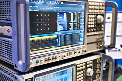
(a frequency signal generator device.)
AD9850 Pinout Description
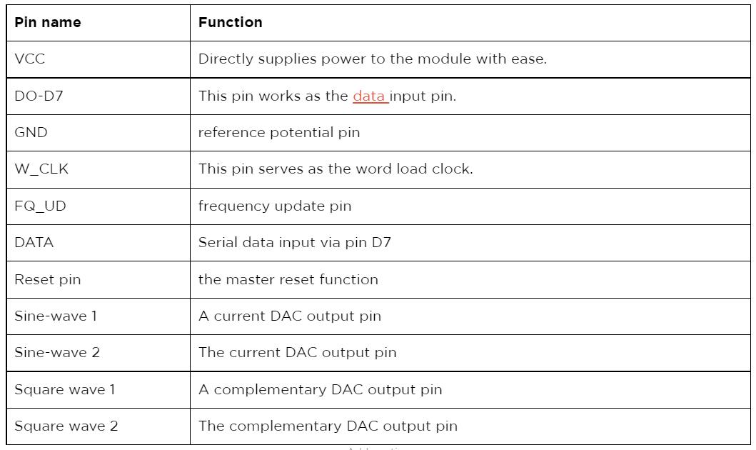
The W_CLK pin in serial mode synchronizes words and loads them to the Arduino via a parallel load mode. The frequency update pin updates the frequency found in the input data register. The update can only occur when the clock experiences a rising edge. Immediately the updating process is complete, and the reset pin resets the pointer to 0.
On the other hand, the function of the data pin is to load serial data. Whereas the device’s reset clears every register apart from the input register of the IC. Notably, it achieves this function by putting the record of the IC into a high state.
(a close-up signal generator of the oscilloscope display.)
AD9850 Features and Specifications
- First, the module uses a DAC current of 0.03A and has an operating voltage of 3.3 to 6V.
- Second, it operates between -40 and 850⁰C.
- Third, it has an oscillator frequency of 125mHZ.
- Additionally, its power dissipation entirely depends on the amount of power supply.
- Also, the module has an output frequency of between 0-40mHZ.
- Moreover, it has a comparator that generates minimal jitters in a square wave output.
- Lastly, it has a source or a sink continuous current of 0.005A.
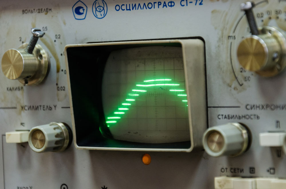
(an oscilloscope showing a wave pattern.)
Alternative Products
The two main AD9850 alternative generator modules include the AD9833 signal generator and the ICL8038 signal generator.

How to Connect and use the AD9850 Module?
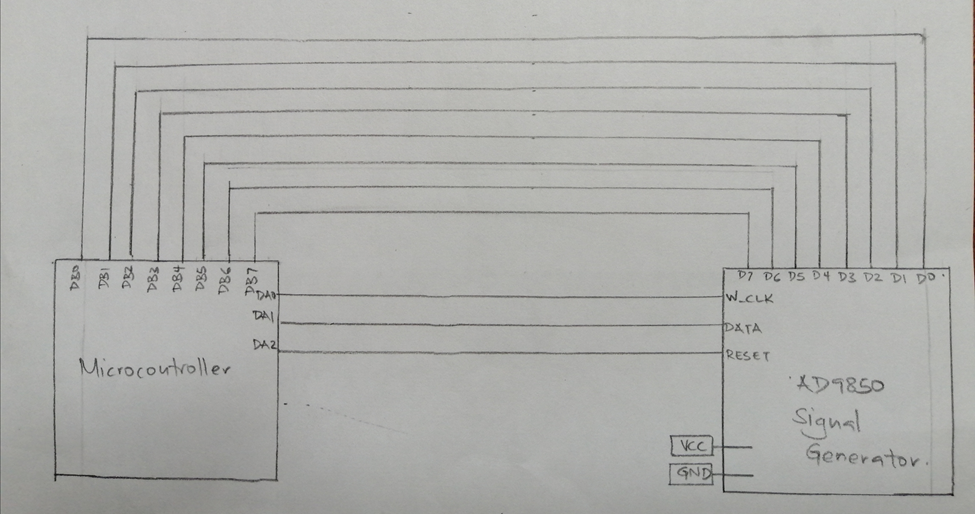
(Diagram of the AD9850 connection system)
To connect the AD9850 module with external components, all you require is any microcontroller. Also, ensure you have a breadboard, jumper wires, an Arduino Uno board, and most importantly, an AD9850 DDS synthesizer.
Connection
The initial step is to connect the Arduino and the AD9850 SGM. Therefore, connect the 5V pin of the Arduino to the power supply pin of the AD9850 IC. Next, your D13 pin connects to the word load clock. And the D8 pin on the Arduino to the FQ-UD. After, respectively connect the D10 and D9 pins of the Arduino to the data and the reset pins on the module. Finally, your ground pins on both devices connect, establishing a firm system earthing.
After the connection process, install an AD9850 DDS signal generator module library in an Arduino IDE. The process involved in successfully installing the library is first to open the Arduino IDE. Then, click on Tools, and select the managing libraries option.
After that, on the search bar, type in AD9850. You will receive several drop-down options, but you must choose AD9850_SPI. Once this happens, you will see an install option, click on it, and the module should begin to download.
Code
Significantly, add the following Arduino code once you complete downloading the software.

(Image of an AD7850 module code.)
You should expect the code to run, therefore powering the Arduino. Immediately the Arduino has power, and the DDS signal generator module automatically generates a squarewave one and sine wave one output frequency. Also, you will observe the wave patterns through an oscilloscope.
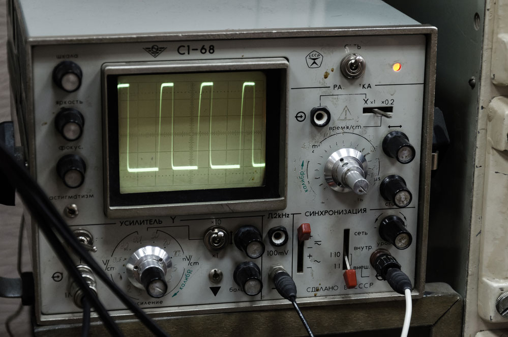
(close-up photo of an oscilloscope.)
Applications
- First, work as a generator of waveforms.
- Secondly, it helps to build communication systems.
- Thirdly, works on projects that require the use of clocks.
- Lastly, you can apply the module in analog to digital converters.
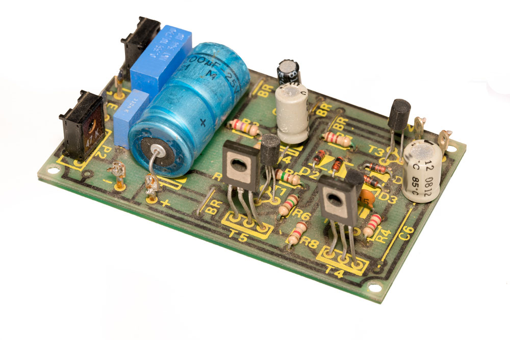
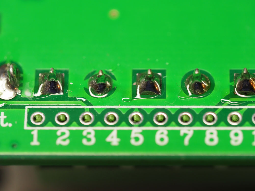
(a circuit board with an analog signal generator.)
Summary
We’ve given information on what the AD9850 DDS signal generator module does, its connections, and how they work in this article. If you’re interested in learning more about your module-related projects, contact us! Our team is always happy to answer any questions from you.


