Necessity is the mother of invention; as time changes, we develop and appreciate smaller and more accurate devices. The AS5600 is one such magnetic rotary position sensor device. Additionally, you’ll enjoy its simple programming and ease of use. Therefore, we at WellPCB highly recommend the sensor for your project. Here, we’ll learn everything about the AS5600.
Contents
What’s an AS5600?
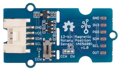
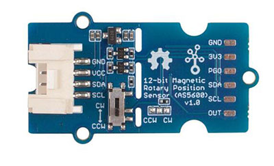
Fig 1: An AS5600 rotary position sensor
The AS5600 is an easy-to-program magnetic rotary position sensor with PWM output or 12-bit high-resolution analog output. It uses a contactless system to measure the absolute angle of a diametrically magnetized on-axis magnet.
Additionally, its durable and robust design removes the effects of any homogenous external stray magnetic fields. Therefore, it’s best for contactless potentiometer tasks.
AS5600 Pin Configuration
The AS5600 has seven pins, as shown below.
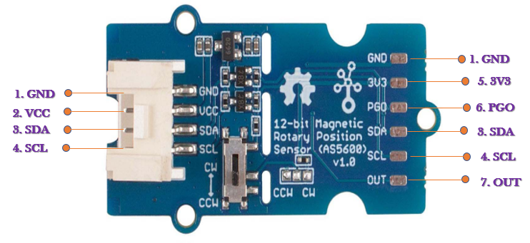
Fig 2: AS5600 pin configuration
- GND: Connect this pin to the system ground for earthing purposes.
- VCC: Power supply pin, 5V/ 3.3V.
- SDA: Serial date of the inter-integrated circuit (I2C).
- SCL: Serial clock of the I2C.
- VCC: 3V3 only power supply for the IC.
- PGO: Used to set the initial and end positions of the rotation angle.
- OUT: Outputs the duty cycle signals as configured by software.
AS5600 Features
Here’s a brief introduction to the features of the AS5600 rotary magnetic position sensor.
- First, it supports contactless angle measurement.
- Second, it has an easy user-programmable start and stops position over the I2C interface.
- Third, it has a 12-bit digital to analog conversion (DAC) output resolution.
- Fourth, you can program the maximum angle from 18 to 360 degrees.
- Fifth, it automatically detects a magnetic material or surface.
- Sixth, it supports easy-to-start and stops position programming without a programmer in a 3-wire setup.
- Seventh, it enters into low-power mode automatically when necessary.
- Finally, it has analog output radiometric to pulse width modulation (PWM) or VDD-encoded digital output.
AS5600 Specification
- It has a supply voltage of either 3.3 or 5V.
- Its input current ranges up to 100mA.
- Also, it has an operating ambient temperature of -40 to 125°C.
- The AS5600 has an I2C non-changeable interface with address 0X36.

AS5600 Working Principle
The AS5600’s working relies on the Hall effect. It is because it has a built-in Hall sensor that detects changes in the magnetic field’s direction.
Furthermore, with assistance from the 12-bit internal A/D, the magnetic field direction is amplified by an amplifier.
Hence, the AS5600 module can produce 4096 positions each round. Also, you can choose to export RAW data via the I2C interface or PWM wave through the OUT pin. Moreover, the maximum angle is likewise programmable.
You may configure it to be anything between 18° and 360°, meaning the measured angular accuracy is about 18/4096.
However, you must know that the AS5600 can only work well with a magnet similar to your chip size.
Also, you should measure the module while keeping it very close to the magnetic field. Another vital point is that you should align the AS5600 sensor center with that of the magnetic field. Hence, the vertical distance should range from 0.5mm to 3mm.
Play With Arduino
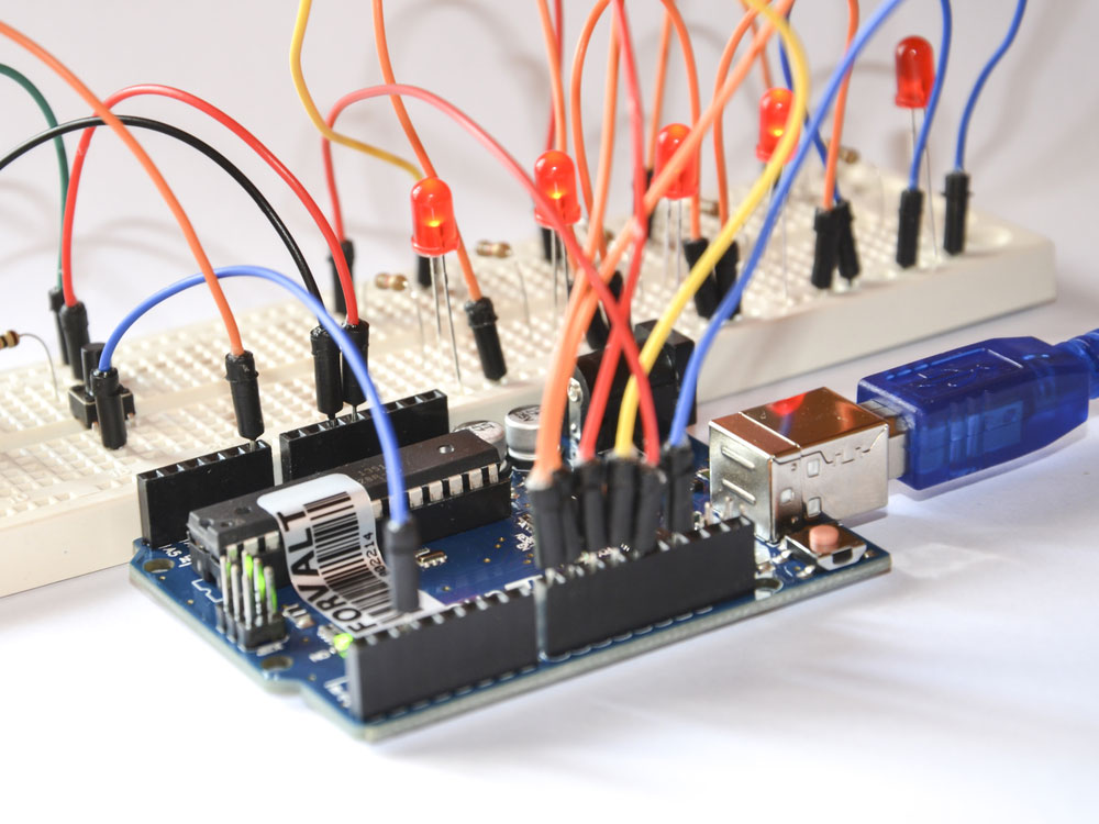
Fig 3: An Arduino platform for developers
For this setup, you’ll need an Arduino board or Seeeduino V4.2, a base shield, and an AS5600.
Here’s how you can configure your setup.
Hardware Connection.
- First, connect the AS5600 to the base shield’s I2C port.
- Second, connect the Grove base shield to your Seeeduino board.
- Third, connect the board to your PC using a compatible USB cable.
Software Connection
- The first step involves downloading the AS5600 library from Github.
- Second, restart your Arduino IDE and open the readAngle through File → Examples → Seeed_AS5600-master → readAngle.
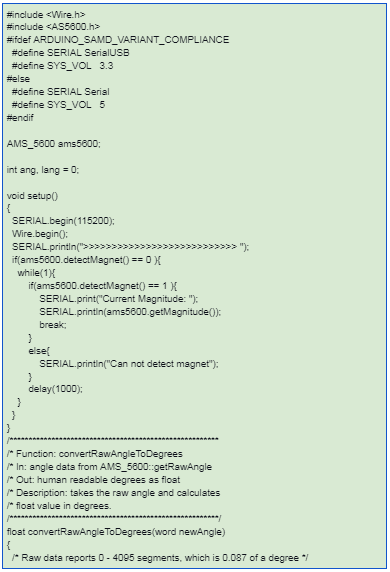
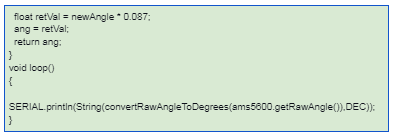
- Here’s an example of the readAngle code.
- Third, upload the demo.
- Fourth, open the Serial Monitor of Arduino IDE from the Tool option and set the baud rate to 115200.
- Fifth, test your system to see if it reads on your screen as you move the sensor.
AS5600 Application
Here are some applications of the AS 5600 sensor.
- Home appliances
- Contactless knobs
- Pedals and RC servos
- Contactless potentiometers
- Also, controlling volume for audio devices
- Developing automation
- Additionally, AS5600 work as automotive controls
Conclusion
The AS 5600 is an excellent alternative to the traditional potentiometers as it’s non-contact and high-precision. And as we’ve seen, they work well in measuring, controlling, and positioning projects.
If you have one and would need any assistance, feel free to contact us. We’ll get back to you as soon as we can.


