
Contents
What Do You Need to Make a Radio Frequency Jammer

Figure 1: A Satellite receiver
A jamming circuit is imperative to block radio communications from reaching a particular receiver.
Thus, it also prevents the misuse of flux and solder. To make this component, you require the following components:
- A heatsink
- A flyback driver
- Hard paper
- Glue
- Paraffin Wax
Radio Frequency Jammer Circuit Design
Check out the circuit diagram below.
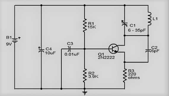
Figure 2: A Radio Frequency Jammer Circuit Diagram
Circuit Explanation
A simple jammer circuit can perfectly jam a wide range of radio frequency signals between 5 and 10 meters.
An ideal radio frequency jamming equipment features 22pF trimmers to facilitate effectively blocking the RF noise signal.
Secondly, it should cover the frequency range of 50 MHz to 1 GHz. However, compelling it to jam signals from a frequency range of 500 MHz will most likely cause stability issues.
How to Make a Radio Frequency Jammer

Figure 3: A Telecommunications Tower
The following are the critical steps to making a practical radio jammer kit/ RF signal jammer circuit.
Make the driver circuit.
- First, you must wind the primary and secondary coils in the same way. Also, installing a fast diode that will shield the transistor from a voltage surge and voltage drop is imperative.
- Next, you must also use a relatively large heatsink. A small heatsink induces heating of the transistor within a short period.
- Besides, don’t use solder to connect the flyback circuit’s primary and secondary coils to the driving circuit. Instead, use screws, as this will aid the installation of different flybacks.
Flyback Preparation
- Create a rigid paper cylinder, and connect the primary and secondary coils using glue.
- During the above process, ensure the ferrite cores are placed correctly with plastic plates between them. It will significantly reduce the ultrasound vibrations.
- Ideally, your coil should measure 1mm in thickness and 0.1 mm for the magnetic wire. Also, ensure the windings lack an internal arc. Besides, it is imperative to presoak your coil in paraffin wax.
- On average, the secondary will give 8 – 9 mm sparks, requiring a 20W power supply.
- If you intend to have more wattage on the secondary, ensure you use something secondary. The secondary voltage, in this case, will be too much for the primary coil. Besides, it’s also advisable to use epoxy rather than paraffin, as it’s more resistant to melting.
Input the Antenna

Figure 4: A transmitter antenna icon
- Before installing the antenna, the sparks were 2-3 mm. Nonetheless, the voltage drop will increase the spark length to approximately 8mm if you use an antenna measuring 2 meters.
- This pre-made jammer will operate at a range of 10-15 meters. But for an RF jammer compatible with longer ranges, you can increase the length of the antenna.
- Besides, note that MW noises at longer distances are significantly likely. But, the VHF noise is most prevalent at a range of 8-10 meters.
- Apply secondary coils to extend the homemade RF signal jammer’s range. Also, boosting the functioning of performance drivers can significantly improve the radio frequency jamming system.
How to Peak the Resonance
You can achieve the peak resonance of the jammer via the following key steps:
- First, attach a DC voltmeter to the point test and groundline. The ideal voltmeter for this function measures 0 -10 volts.
- Next, tinker with the 22p trimmer till you obtain a maximum meter reading of 3V. Note that this change may impact the initial frequency of the jammer.
- Hence, fine-tune the 22p trimmer to shift the obtain back to its proper frequency.

RF Jammer Coil Specifications
Your RF jammer is a complicated device and may not be compatible with other frequencies. Thus, to change this, you need to tweak the diameter and number of coils of the primary and secondary coils. Also, tinkering with the adjacent trimmers is a prerequisite for efficient circuit jamming.
Also, using a high-quality PCB in constructing your RF jammer is advisable.
Bonus Tips & Knowledge About Radio Frequency Jamming System
There’s limited use of radio frequency jamming devices in Europe, while in countries such as the US, they are banned.
However, some nations have no laws governing these digital devices.
All in all, some manufacturers are already making electronic devices for RF jamming purposes. It is irrespective of the common notion that the devices are not suitable.
But despite the reservations jamming equipment is necessary as it has a variety of applications.
Radio Frequency Jamming APP

Figure 5: Using an RF Jamming App
Numerous models of cell phone jammer applications are handy in detecting the presence of jamming devices.
A mobile cell phone or similar electronic gadgets cannot make a call when a jamming device is present, as the jamming device impacts the cell phone receiver.
Thus, installing such an app makes you aware of the nearby influential radio frequency jammer devices.
Conclusion
As this article highlights, you can easily create a jammer circuit to prevent the malicious interference of radio frequencies.
That’s all for now but for additional inquiries, contact us.


