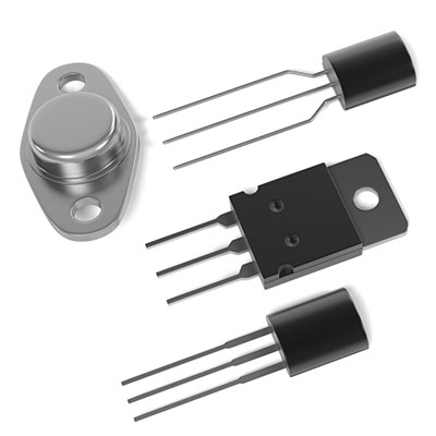
(BJT power transistor symbols)
In today’s article, we will learn how transistor switches work and outline other examples of transistor switches operating outside of BJTs.
Contents
Operating Characteristics of Transistor
Transistor switches usually have two areas of operation, which include;
- Cut Off Region
When operating your transistor in the cut-off region, you must reverse bias both junctions first (base-collector junction and base-emitter junction).
Also, the ground input base current is at zero potential (IB=0).
Then, the operating conditions of your transistor should be as follows;
- The output collector current IC = 0 A and output voltage VOUT = VCC
- The VBE is less than cut – in voltage 0.7V
- VOUT = VCE = VCC = “1”
There is no current flow through the device since there is a large depletion layer on the transistor’s junctions. Therefore, the transistor functions as an open switch/fully off.
- Saturation Region
Here, a forward bias is the BJT’s emitter and base junction. Next, connect the input to VCC.
Operating conditions;
- A cut-in voltage level lesser than base-emitter voltage.
- The collector current is at a maximum.
- Maximum collector current flows (IC = Vcc/RL).
- Base-emitter voltage VBE is more significant than 0.7V.
Forward biasing results in a small width of the depletion layer, which consequently causes a minimum collector-emitter voltage drop.
As such, you’ll operate the Bipolar Junction Transistor as a closed switch/fully ON since the current flowing through it has a maximum value.
Transistor as a Switch Circuit Diagram
NPN Transistor Switching Circuit
A switching operation using an NPN transistor only works when you supply voltage to the base terminal to the transistor.
Moreover, when a voltage is applied between the ground and emitter, the emitter-to-collector voltage becomes zero, causing a short circuit.
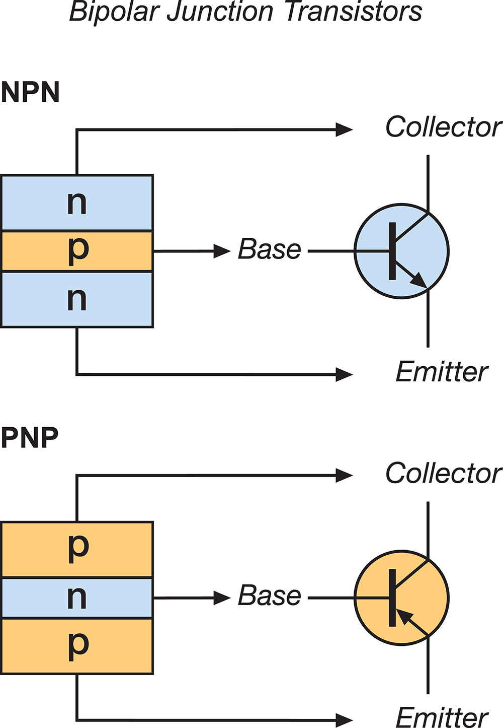
(NPN transistor)
Then, if you apply a zero-input voltage, the transistor functions in the cut-off region, becoming an open circuit. Next, you can choose a reference point to connect a load to its switching output.
Finally, turning on the NPN transistor will cause the load to flow from source to ground. However, the base input terminal has to be more favorable than the emitter by about 0.7V to enable the base current to flow.
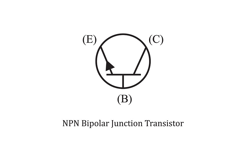
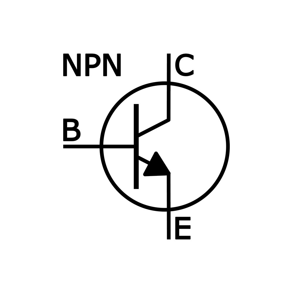
(NPN BJT symbol)
The transistor enters saturation mode when the maximum current (collector) flows through it.
PNP Transistor Switch
A PNP transistor (a mechanical switch) often works similarly to an NPN transistor. But, the current in the PNP transistor flows through its base.
Thus, it is ideal in operating configurations having hostile grounds.
Furthermore, based on its emitter, the PNP transistor’s base terminal is often in a negative bias mode. That means that the current flow will occur with a negative base voltage.
You require a reference point to connect your PNP transistor to its switching output.
In that way, switching on the transistor enables current to flow from the source to the ground.
Digital Logic Transistor Switch
Further, you can combine transistors to make logic gates such as NOT, OR, and NAND. However, a MOSFET integrated circuit is preferable to BJTs since it is more power-efficient.
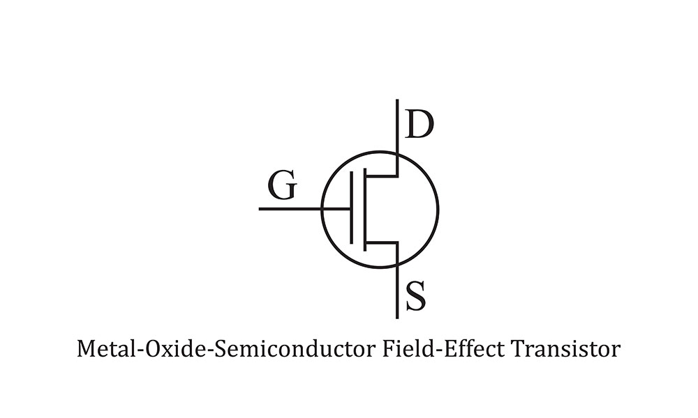
(MOSFET symbol)
- Circuit Overview
A base resistor in the circuitry limits the logic gate’s output current.
- Darlington Transistor Switch
Sometimes, you’ll use multiple switching transistors to switch the load voltage or current directly since the transistor’s Direct Current gain is low.
Hence, you’ll use an input transistor to turn off and on a larger current that handles the output transistor.
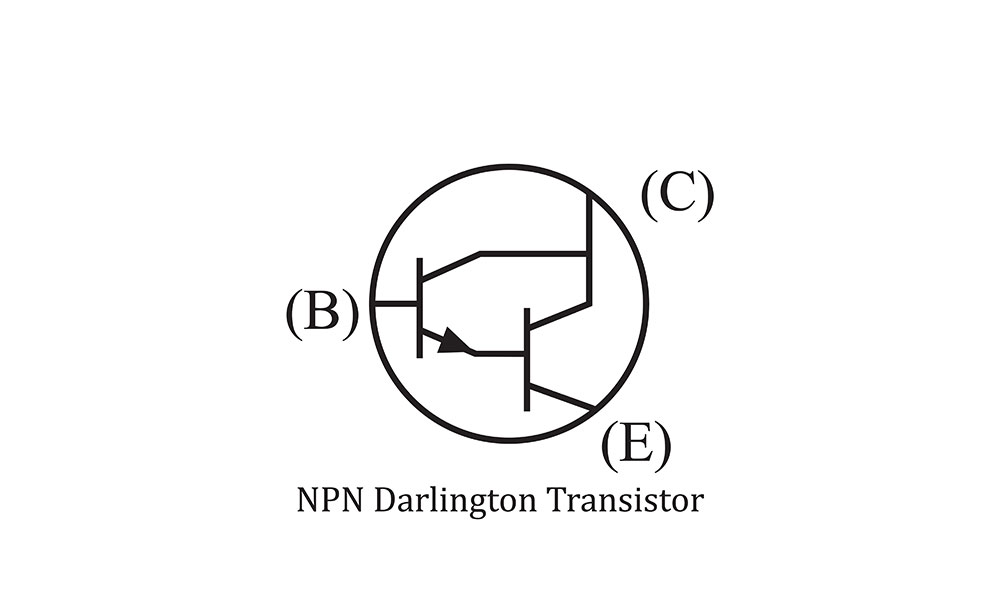
(NPN Darlington transistor symbol)
Generally, Darlington transistors comprise two connected bipolar transistors, PNP and NPN. Their connection ensures a multiplication of the first transistor’s current gain and the second transistor’s current gain, yielding a high current gain as one transistor unit.
- Circuit Overview
First, the input/first transistor receives an input signal at its base. Then, the signal amplifies before driving to an output/second transistor.
Next, the signal amplifies further to generate a very high current gain.
Since Darlington transistors have high switching speeds, they can be used in stepper motor/DC motor control, lighting circuits, and inverter circuits.
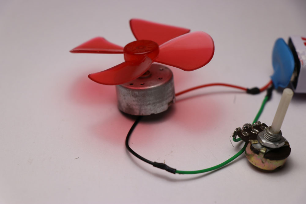
(DC motor)

Transistor as a Switch
We will now show you how you can practically use transistors as switches.
- Transistor to Switch a Light-Emitting Diode
In our first example, we will switch on an LED bulb.
- Circuit Overview
When you open the switch at the base terminal, there will be no current flow at the base. Therefore, the transistor will be in a cut-off state.
As such, the LED is off since the transistor functions as an open circuit now.

(LED bulb)
On closing the switch, you’ll enable the base current to flow through the transistor. Then, saturation will increase, which will ultimately turn on the LED.
Note: resistors in this circuit limit the current flowing through the LED and base. Additionally, you can modify the LED’s intensity by varying the base current path’s resistance.
Transistor to Operate the Relay
Secondly, you can have a small transistor circuitry to operate a relay.
- Circuit Overview
Here, the circuit is as follows;
If you apply an input at the base, you’ll drive the transistor into the saturation region. Consequently, the circuit experiences a short.
In the process, you’ll energize the relay coil and then operate the relay contacts.
Moreover, suddenly removing power in inductive loads (inductors and motors) results in a high-potential relay coil crossway.
The high voltage may destroy other circuit components. Thus, a diode parallel to the load prevents damage from highly induced voltages.
- Transistor to Drive the Motor
Lastly, using a transistor to drive a motor unidirectionally by turning on the transistor at regular time intervals.
- Circuit Overview
Applying a flywheel diode prevents damage to the DC motor (an inductive load).
Then, switch on the transistor in saturation, and cut-off regions continually turn off and on the motor.
Note: You can switch the transistor at variable frequencies to control the motor speed from a standstill to full speed. You can also obtain the switching frequency from ICs or control devices like MCUs.
Conclusion
The article above gives concise information on the characteristics, types, operating regions, and applications of switching transistors.
If you need any clarification concerning the topic, kindly contact us.


