Most DIYers and engineers prefer raw binary output over decimal coded output—in many cases.
In this regard, there are many available counter-integrated circuits that are easy to create or buy. But, most of these counter ICs have raw binary output. That’s where the IC 4017 decade counter comes in. So, the concepts surrounding the circuit are easy to understand. But, if you’re finding it hard to comprehend, you’re in the right place.
In this article, we’ll show you everything you should know about the IC 401 and break it down into understandable bits. And if you have little or no knowledge of IC packaging, this article is also for you.
Are you ready? Let’s dive in.
Contents
What is IC 4017
The IC 4017 is a CMOS decade counter that works effectively for low-range counting applications.
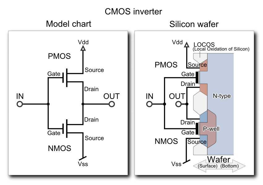
Cmos Inverter
As an electronic circuit, the IC 4017 can add from 0-9 (10). That’s why it’s called the decade counter. Also, the output from this circuit comes in decoded format.
Also, this circuit has ten outputs, and they come with a high sequence in response to a high clock pulse. Plus, the input clock pin of the IC 4017 applies this pulse.
In other words;
All ten outputs, from start to finish, go through a one cycle high output sequencing. And it responds to the ten-clock pulse it receives at its input pin. Also, the IC 4017 counts and divides the input clock by ten.
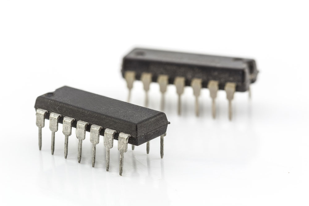
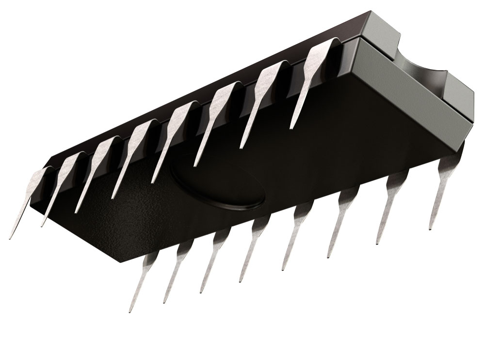
Integrated Circuits isolated with 17 pins
Moreover, the circuit is excellent for running LED projects. Thus, beginners use this LED-based circuit to run lights.
In the end, you can say the IC 4017 is one of the most flexible counters out there. Plus, it’s easy to make and includes a counter as well as a decoder.
What Are the Features of IC 4017?
Here are some of the features of the IC 4017:
- Supplies a voltage of 3v – 15v
- It has compatibility with the transistor-transistor logic (TTL)
- It has a running speed of 5 Mhz
- You can use the IC 4017 for electronic devices, alarms, automotive devices, and even electronic instrumentation devices
IC4017–IC 4017 Pin Description
The IC 4017 has 16 pins that serve different purposes. So, ten pins serve as output pins, while the other six pins are input pins.
Integrated circuit with 16 pins
So, let’s dive deeper into the descriptions and functions of these pins:
IC4017–Output Pins of IC 4017(Pin 1 to 7 & 9 to 11)
The output pins of the IC 4017 are pin 1-7 and 9 -11. These pins change to ‘high’ level one after the other. Thus, for every clock signal, the level of each pin increases sequentially.
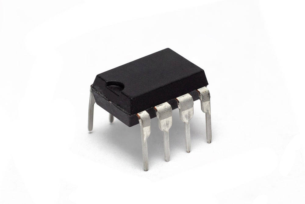
8 pin integrated circuits
IC4017–The Enable Pin/Clock Inhibit(Pin 13)
As the name implies, the “enable pin” validates the IC 4017, when active, to turn down low.
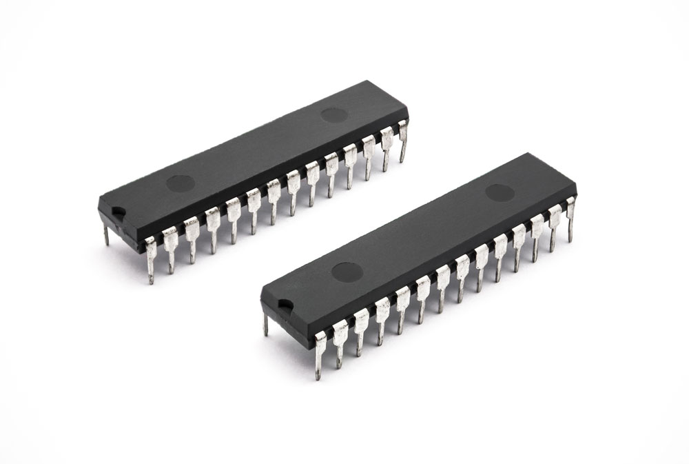
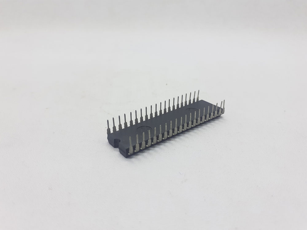
Integrated circuits with 28 pins
So, if you want to disable it, you need to switch off the IC. Then, for the pin to work, you need to connect it to an active high input. And when the enabling pin is active (high), it disregards all clock signals.
Clock Pin(Pin 14)
The clock signal for Pin 14 is accountable for the sequential output.
Hence, when the circuit detects the first clock pulse, pin 3 drops low, while pin 2 goes high for the nest clock pulse. Then, it forms a sequence.
Most importantly, if there is no clock signal connected to the input pin, you must connect it to a negative or positive voltage supply.
Plus, this clock input pin (pin 14) only responds to a positive voltage or positive clock signal.
IC4017–Reset Pin(Pin 15)
Pin 15 is responsible for resetting the sequence’s output when the count reaches 10. When this happens, the sequence’s output is set back to its normal state.
So, join the reset pin to the ground if you want it to work.
Why Pin 15 Should be Grounded?
The sequencing and resetting of this circuit can only be successful if pin 15 is grounded or kept at logic low. Otherwise, the IC will malfunction. The sequencing will not happen if you keep pin 15 at logic high.
IC4017–The Ground & Supply Pin(Pin 8 & 16)
Pin 8 serves a purpose as a ground for the circuit. So, it would be best if you connected it to a negative voltage supply. But, on the other hand, pin 16 is the supply pin for the IC4017. Hence, the best thing to do is to have a positive voltage supply.
IC4017–Carry Out Pin (Pin12)
Pin 12 receives a supply of the carryout signal, which completes an entire cycle for every ten-clock cycle. Also, it ripples the IC; in other words, it delays the IC’s counting operations.

IC4017–How Does IC 4017 work?
Here’s an easy but detailed process of how the IC 4017 works:
First, if you feed a frequency of 10Hz, the input pin 14 will be equally divided between the ten outputs. So, this will turn ON and OFF the other outputs once per second.
For each output, there is a buffer that can drive LEDs. Also, you can find the buffer gate inside the IC. Plus, it doesn’t require any external circuits.
The output pins aren’t the only vital pins. The reset and clock enable pins are equally important. These pins must be connected to a high or low logic because they are control pins.
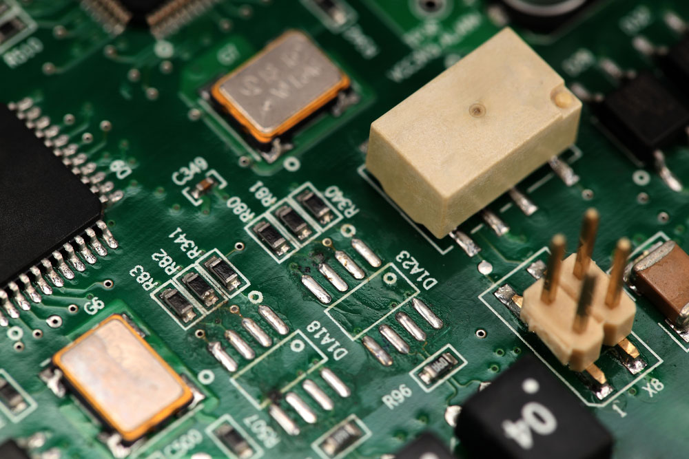
4-pin integrated circuit mounted on a PCB
IC4017–How to Cascade the 4017 counter
You can cascade two or more IC 4017 counters to make one counter.
Usually, it can be a pre-set counter that sends its output to a signaling device like bells or lamps. So, you can arrange the circuit to produce a forward reading display and also increase the range.
Next, use the carryout pin 12 to connect to the clock of the next counter. Finally, ensure the reset and clock inhibit pins connect to the ground.
What Are the Applications of IC 4017?
Industrial Integrated circuit
The applications of IC 4017 include:
- LED applications
- Frequency division
- Decade counter
- Binary counter
- Light Chaser
- Remote controlled switch
- Matrix Die
- Touch ON-OFF switch
- Automotive
- Electronic manufacturing of medical instruments
- Counting applications
Application Circuits of IC4017
Integrated circuit with 28 pins mounted on a board
As mentioned earlier, IC4017 is excellent for LED applications.
So, let’s talk about two application circuits (LED) of the IC4017.
IC4017–Circling LEDs effect
This application allows you to have LED lights (up to 8), which light up one after another. Thus, this process forms a circling effect.
Glow LED lighting with the curling LED effect
Here’s how it works:
The circuit uses a 555 IC that operates in astable mode. Also, it comes with a 14Hz frequency, and the 555 IC in this circuit works as a pulse generator.
What it does is to provide the input clock pulse to the counter IC 4017. Also, it generates approximately 14 clock pulses per second to the IC 4017.
Furthermore, the pulses produced by IC 555 (pin 3) get transferred as input through pin 14.
Whenever the clock input of the IC 4017 counter receives the clock pulse, it starts the count and activates the out pins one by one.
In other words, when the count is 0, that means pin 3 is high. And it lights up LED 1, and the other LEDs will be off. The process continues according to the pin functions mentioned earlier.
In Summary
That’s everything about the IC 4017. Other things worth mentioning are the logic high and logic low. Logic high means a supply of positive voltage, while logic low refers to a negative voltage supply.
Overall, the IC 4017 is the best option for any project that requires counting to 10.
So, if you need more information about this circuit, feel free to reach us today.


